A Ford F-150 rear window defroster that is not working usually has an open fuse, failed relay, damaged heating grid, disconnected glass terminal, or poor contact in a power-sliding window. Test the control signal and supply voltage before repairing the glass, because a dark button, cold grid, and partially heated grid indicate different faults.
Key Facts at a Glance
- The Ford F-150 rear defroster uses conductive heating traces bonded to the inside of the rear glass.
- A blown fuse usually indicates excessive current or a short, not merely an old fuse.
- A power-sliding rear window adds motor, latch, contact-pin, seal, and position-sensor failure points.
- A grid repair kit can fix a narrow trace break, but it cannot restore a detached terminal or failed slider contact.
- Fuse numbers and ratings differ by model year, engine, body style, and trim; the owner’s manual and fuse-box label control.
- A rear defroster circuit can carry substantial current, so never install a larger fuse or use an unfused jumper.
How Does the F-150 Rear Defroster Work?
The Ford F-150 rear defroster converts electrical energy into heat through parallel conductive traces printed across the inside of the glass. Battery power passes through a fuse, switching hardware, wiring, glass terminals, the grid, and a ground path; the HVAC or body-control system determines when the circuit can operate.
Most F-150 systems use a timed operating cycle rather than continuous heating. The exact timer and control strategy vary by generation. Some trucks use a relay and dedicated switch logic, while newer trucks can use a body control module to command the relay and monitor related inputs.
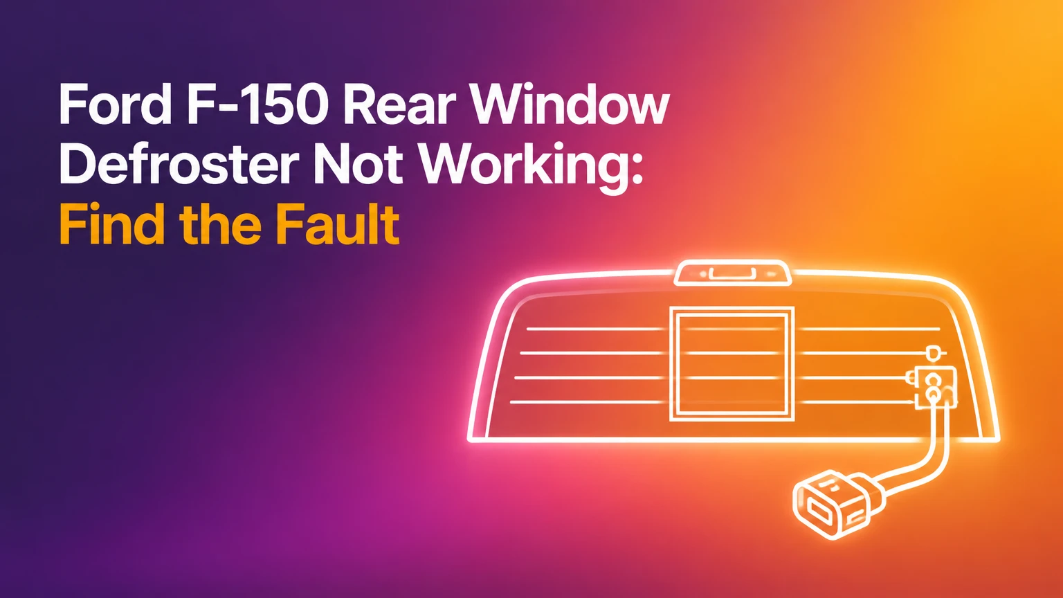
The thin horizontal lines are resistive conductors. Current passing through them warms the glass surface enough to evaporate condensation and loosen frost. The grid is not a conventional wire that can be spliced easily, and scraping the glass can cut several traces at once.
Ford owner manuals commonly warn owners not to use sharp objects on the inside of the rear window. That instruction matters because a razor blade, metal ice scraper, or abrasive pad can create a failure that looks like an electrical problem but is actually mechanical damage to the printed traces.
A typical operating voltage is approximately 12.0-12.8 volts with the engine off and a healthy battery, or 13.5-14.8 volts with the charging system active. Current draw varies with glass design and temperature, so use the factory specification rather than treating 30 or 40 amps as universal.
What Failed: Solid Glass or Power-Sliding Glass?
The first diagnostic decision is whether the F-150 has stationary rear glass or a power-sliding center section. Stationary glass has fewer failure points, while a sliding unit adds moving contacts and mechanical alignment that can interrupt the heater even when the grid itself is intact.
| Rear-window configuration | Extra failure points | Typical symptom | First inspection |
|---|---|---|---|
| Solid stationary glass | 2 terminals, grid, ground, harness | Button illuminates, grid remains cold | Glass tabs and trace continuity |
| Manual sliding glass | 2-4 moving contact interfaces | Heater works only in one position | Closed-window alignment and contacts |
| Power-sliding center glass | Motor, latch, contacts, sensors, harness | Defroster and slider behavior may change together | Fully closed position and fault codes |
| Aftermarket replacement glass | Non-identical tabs or connector | Button works, partial grid heats | Connector, terminal layout, glass part number |
A power slider is not automatically wired in a simple series loop across three panes on every F-150 generation. The wiring arrangement changes by year and supplier, so do not assume that an open center window proves the entire circuit is series-wired. Verify the wiring diagram for the vehicle identification number.
Heated mirror behavior also varies. Some F-150 trims share a defrost command with the heated mirrors, while others use related but separately protected branches. If the mirrors heat but the glass does not, the vehicle may have power at the control side and an open glass circuit. If both stop working, inspect the shared command, fuse, relay, and module inputs first.
Why Is the Defroster Button Dark or Inactive?
A dark or immediately extinguished indicator usually points toward control power, fuse, relay, switch input, a body-control decision, or an open condition that prevents the system from being enabled. A lit indicator with a cold window more often points toward the high-current path, glass terminals, grid, ground, or a relay contact failure.
The engine does not universally have to run for every F-150 defroster test. Some generations permit operation with the ignition on, while others limit heating under battery-saving conditions or require the powertrain to be running. Use the owner’s manual procedure and avoid interpreting a key-on, engine-off result as proof of a failed heater.
Check these basic conditions before removing trim:
- Turn the ignition to the position specified by the owner’s manual.
- Start the engine if the manual requires it or if the battery is weak.
- Close all rear-window sections completely.
- Press the rear-defrost button once and observe the indicator.
- Wait two to five minutes for a measurable temperature change.
- Confirm whether the heated mirrors respond, if the truck has that feature.
A defroster grid may feel only mildly warm by hand. Use a noncontact infrared thermometer, held at consistent distances, or observe narrow cleared bands in condensation. Do not touch exposed probes to adjacent traces while the circuit is energized.
How Do You Test the Fuse and Relay?
Test the designated fuse on both sides with a 12-volt test light or multimeter, rather than relying only on visual inspection. The correct fuse cavity, rating, and fuse-box location differ across F-150 generations, including the 2004-2008, 2009-2014, 2015-2020, and 2021-present platforms.
| Test result | Measurement or observation | Most likely area | Next action |
|---|---|---|---|
| No voltage on either fuse test point | 0 volts with command active | Feed, ignition, control, or test setup | Verify ignition and wiring diagram |
| Voltage on one fuse side only | Battery voltage on one side, 0 volts on other | Open fuse | Replace with identical rating, then retest |
| Voltage on both fuse sides | Approximately battery or charging voltage | Fuse is conducting | Test relay output and glass supply |
| Fuse blows immediately | Fuse opens within seconds | Short, damaged harness, or failed component | Stop replacing fuses and isolate branches |
| Relay input present, output absent | Input voltage present, no switched output | Relay or control signal | Check coil command and relay |
A fuse rating is not a performance setting. Installing a 40-amp fuse where Ford specifies 30 amps can overheat wiring before the fuse opens. If the replacement fuse fails again, the circuit needs isolation and resistance testing.
A relay swap is acceptable only when the replacement relay has the same part number, terminal arrangement, and electrical rating, and the substituted circuit is nonessential. A relay that clicks is not automatically healthy because its high-current contacts can still be burned or resistive.
How Do You Test Power at the Rear Glass?
Measure voltage at the rear-glass connector with the defroster commanded on, using the year-specific wiring diagram and back-probing technique. A supply reading near battery or charging voltage confirms that power reaches the connector, but it does not prove that the glass ground, terminals, or grid can carry current.
Use insulated meter probes and avoid piercing weather seals unless the connector design permits it. On many F-150s, access requires removing a trim panel or folding a seat, but the connector location is not identical across cab styles and generations.
| Measurement location | Typical healthy indication | Meaning of an abnormal result | Diagnostic direction |
|---|---|---|---|
| Fuse input | 12.0-14.8 V | 0 V | Feed or ignition circuit |
| Fuse output | 12.0-14.8 V | 0 V with good input | Open fuse |
| Relay output | 12.0-14.8 V while commanded | 0 V | Relay, control, or wiring |
| Glass supply to ground | Near charging voltage | Low or unstable voltage | Harness, connector, or ground |
| Grid terminal to terminal | Low finite resistance | OL or infinite resistance | Open grid or detached tab |
Resistance testing must be performed with the power disconnected. A complete glass-grid reading commonly falls in the low-ohm range, but the correct value depends on grid size, ambient temperature, and design. An “OL” reading strongly suggests an open circuit, while a very low reading near zero can suggest a short or an incorrect test location.
Voltage-drop testing is often more useful than resistance alone. With the defroster operating, measure from the battery positive terminal to the glass positive terminal, then from the glass ground terminal to battery negative. More than a small fraction of a volt across either side indicates unwanted resistance, although the service manual’s limit takes priority.
How Can You Find a Broken Grid Line?
Find a broken grid trace by inspecting the interior glass in strong side lighting and then testing each suspect line for continuity. A single narrow interruption can stop one horizontal heating line while the rest of the defroster continues to operate.
A typical trace-repair procedure is:
- Clean the area with isopropyl alcohol and a lint-free cloth.
- Mask both sides of the break with tape.
- Apply a rear-defogger conductive repair compound according to its instructions.
- Allow the stated curing period, often 24 hours.
- Remove the tape carefully and test the grid.
Grid paint cannot repair a detached metal terminal, a cracked glass panel, a damaged harness, or a missing spring contact. It also cannot reliably bridge a broad area where several traces and the bus bar have been scraped away.
A useful practitioner rule is to repair only a clearly localized trace break when voltage is present at the glass and most other lines heat normally. If the entire grid is cold, painting individual lines first usually wastes time because the failure is upstream or at a common terminal.
What Should You Check on a Power-Sliding Rear Window?
Inspect the power-sliding window’s closed-position contacts, terminals, seals, latch, and harness before condemning the glass. Dirt, corrosion, weak spring tension, misalignment, or a slider that stops short can interrupt the heater even when the conductive grid is undamaged.
With the ignition off, inspect the contact surfaces for oxidation, bent hardware, contamination, and uneven wear. Confirm that the center pane reaches its fully closed position without forcing the motor. Do not aggressively slam the glass, because impact can damage the regulator, latch, seals, or tempered panel.
Check whether the following symptoms occur together:
- The slider reverses before reaching the closed position.
- The defroster works only after the window is moved.
- The center section has visible play or misalignment.
- The window motor operates but the latch does not confirm closure.
- The rear defroster and heated mirrors stop responding simultaneously.
Clean accessible contacts only with a product approved for electrical connectors and a soft tool. Do not bend spring contacts without a measured repair procedure, because excessive pressure can crack the glass or create permanent misalignment.
Which Repair Fits the Failure?
The correct repair depends on where continuity ends. A fuse or relay is inexpensive, a trace break may need conductive paint, and a detached terminal or failed sliding-glass assembly often requires specialized glass repair or replacement.
| Confirmed fault | Typical parts cost | Typical labor time | Appropriate repair |
|---|---|---|---|
| Correctly rated fuse | $2-$10 | 5-10 minutes | Replace after finding no short |
| Matching relay | $15-$60 | 15-30 minutes | Replace after confirming relay failure |
| One trace break | $12-$35 kit | 30-60 minutes plus cure time | Conductive grid repair |
| Connector or ground fault | $10-$150 parts | 1-3 hours | Repair terminal, harness, or ground |
| Detached glass terminal | $100-$300 specialist repair where supported | 1-3 hours | Approved glass-terminal repair |
| Complete rear glass | $300-$1,600 installed | 1.5-3 hours | Replace compatible glass assembly |
These are typical North American retail ranges, not Ford-authorized quotations. Labor varies by region, cab configuration, glass availability, tint, privacy shading, and whether the replacement includes a power slider.
A conductive paint repair offers the best value for a short, isolated line break. It is a poor choice when the bus bar is detached or when the glass has multiple damaged areas. Complete glass replacement costs more, but it restores the integrated terminals, seals, and grid when the assembly is beyond localized repair.
Aftermarket glass can reduce parts cost, but connector shape, tint, privacy shade, antenna features, slider hardware, and terminal placement must match. Confirm the part number by VIN and equipment before scheduling installation.
Can You Bypass the Rear Glass Circuit?
A permanent harness bypass is not a recommended general repair because it can disable the rear defroster, defeat factory circuit protection, or alter heated-mirror operation. Never install a bare jumper wire, oversized fuse, or improvised bridge across a connector.
Some older F-150 owners discuss isolating a failed glass circuit to preserve another accessory. That approach is vehicle-specific and should be performed only from a verified wiring diagram, with correct fuse protection and a clear understanding of which loads remain connected.
The safety concern is electrical load. A bypass can make a damaged grid or shorted terminal appear functional while moving excessive current through wiring not designed for that configuration. A Ford dealer or qualified automotive electrician can determine whether a documented repair procedure exists for a particular year.
Do not use household epoxy or superglue on a glass electrical terminal. Most ordinary adhesives are electrical insulators and may prevent a reliable connection; some can also soften under heat or damage the terminal bonding surface.
What Are the Most Common Diagnostic Mistakes?
The most common mistakes are replacing fuses repeatedly, scraping the glass, assuming all F-150 generations use the same circuit, and condemning the window without checking the connector under load. Each mistake can increase cost or create a second fault.
Replacing a blown fuse without finding the cause
A single fuse can fail from age or an intermittent event, but repeated failure usually indicates a short, excessive load, damaged harness, or failed component. Replace the fuse once with the exact rating, then stop if it opens again.
Testing resistance while the circuit is powered
An ohmmeter sends its own test current through the circuit. Connecting it to an energized defroster can damage the meter or produce a misleading reading. Disconnect the glass connector and isolate the circuit first.
Treating every cold grid as a broken trace
A cold grid with no voltage at the glass points upstream. Conductive paint cannot repair a missing relay output, open ground, or failed slider contact.
Cleaning the glass with a razor
The printed traces are thin and vulnerable. Use a soft microfiber cloth and a glass cleaner that does not leave an oily film, applying pressure parallel to the traces rather than across them.
Assuming heated mirrors prove the rear grid is powered
Mirror and glass circuits can share a command but use separate branches, fuses, or control paths. Mirror operation narrows the diagnosis, but it does not establish glass-terminal voltage.
How Much Time Does Diagnosis Usually Take?
A basic visual and fuse inspection takes 10-20 minutes, while connector voltage and grid continuity testing usually takes 30-60 minutes. Glass replacement commonly requires 1.5-3 hours, followed by adhesive cure time specified by the glass installer.
| Job | Typical DIY time | Typical professional price | Main variable |
|---|---|---|---|
| Fuse and relay check | 10-30 minutes | $30-$100 diagnostic fee | Access and scan-tool use |
| Connector and grid diagnosis | 30-90 minutes | $100-$250 | Trim removal and wiring access |
| Conductive trace repair | 30-60 minutes | $75-$200 | Number and location of breaks |
| Terminal or harness repair | 1-3 hours | $150-$450 | Glass design and access |
| Rear-glass replacement | Not recommended for beginners | $300-$1,600 installed | Glass type and labor region |
Use these ranges for planning only. A dealership quote may exceed an independent auto-glass specialist’s price, while insurance comprehensive coverage may reduce the customer’s cost if the failure is connected to glass damage and the policy includes the relevant coverage.
When Should You Stop DIY Troubleshooting?
Stop DIY work when the fuse repeatedly blows, the glass terminal has separated, the glass is cracked, the slider is binding, or trim removal risks curtain-airbag damage. A qualified technician should handle structural glass replacement and any circuit that remains hot or shorted after component isolation.
A rear window replacement must use compatible urethane, correct primer, proper glass-setting procedures, and the required cure time before driving. Poor installation can cause water leaks, wind noise, glass separation, or damage to surrounding trim.
Warranty status also matters. Newer trucks may have coverage for electrical components or glass-related defects depending on the warranty, service history, and failure mode. Photograph the glass terminals, grid, connector, and fuse before authorizing repair, then ask the Ford service department to check open campaigns and technical service information for the VIN.
FAQ
Does the F-150 rear defroster work with the engine off?
Some F-150 generations permit rear-defroster operation with the ignition on, while others limit operation through battery-saving or body-control logic. Start the engine for a stable charging voltage, but consult the owner’s manual before treating key-on, engine-off behavior as a fault.
Why does only part of my F-150 rear window heat?
A partially heated F-150 rear window usually has one or more broken horizontal traces, a damaged bus bar, or a localized terminal problem. If the heated area changes when a power slider moves, inspect the moving contacts and closed-position alignment before applying conductive paint.
Can a rear defroster fuse look good but still fail?
A fuse can appear intact while having poor contact at its terminals or losing power from an upstream feed. Test both fuse test points with a test light or multimeter while the defroster command is active, then verify voltage at the relay and glass connector.
Does the rear defroster control the heated mirrors?
The rear defroster button may command heated mirrors on some F-150 trims, but the mirror heaters are not universally wired in the same circuit as the rear glass. Mirror operation is useful evidence, not proof that the glass grid has power and ground.
Is conductive paint safe for a rear-window grid?
Conductive paint is appropriate for a short, clean break in a printed heating trace when the product is designed for automotive rear defoggers. It is not suitable for detached terminals, cracked glass, damaged bus bars, or a power-slider contact failure.
Will insurance pay for a failed F-150 rear defroster?
Insurance may cover rear-glass replacement when covered physical damage caused the failure, subject to the comprehensive deductible and policy terms. Internal electrical failure or gradual grid deterioration may not qualify, so obtain the insurer’s decision before ordering glass.
The Bottom Line
When a Ford F-150 rear window defroster is not working, begin with the correct fuse, relay command, glass-supply voltage, ground path, and grid continuity. Then separate stationary-glass faults from power-slider contact faults. Repair a single trace with conductive paint, repair wiring or terminals with approved methods, and replace the complete glass when the assembly, contacts, or bonding surfaces have failed. Never bypass the circuit with an unfused jumper or install a larger fuse.