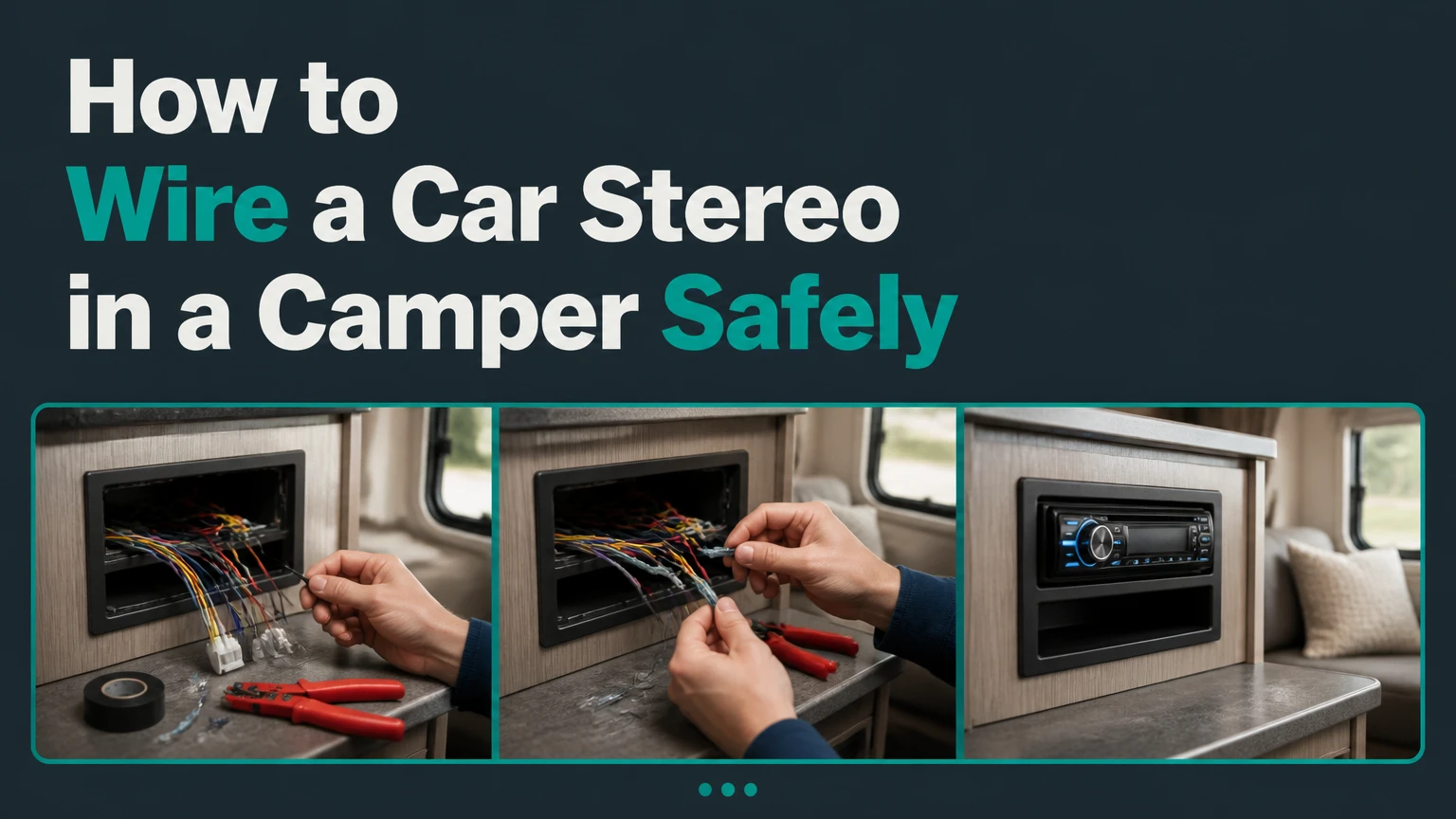
To wire a car stereo in a camper, connect the yellow memory wire to a fused, constant 12V house-battery circuit, connect the red accessory wire to a switched 12V feed, and connect the black ground wire to the negative bus bar. Add the speakers, verify polarity, and test voltage and standby current before securing the head unit.
Key Facts at a Glance
- A camper car stereo normally runs from the 12V house battery system, not the engine-starting battery.
- The yellow wire needs uninterrupted 12V power to retain clock settings, presets, and configuration memory.
- The red wire needs switched 12V power to tell the stereo when to operate.
- A fuse belongs close to the 12V fuse block, and its rating must match the stereo manufacturer’s specification.
- Typical head-unit installation takes 2-4 hours and costs about $40-$150 in wiring and hardware, excluding the stereo.
- A stereo’s actual standby draw varies by model, Bluetooth settings, USB circuitry, and wiring, so a multimeter measurement is more reliable than a generic current estimate.
How Does a Camper Stereo Power System Work?
A camper stereo power system converts the usual automotive ignition arrangement into a house-battery circuit with a permanent memory feed and a controlled operating feed. The camper’s 12V distribution panel supplies power, the red lead is switched manually or by a control circuit, and the black lead returns current through the negative bus bar.
A car alternator normally supplies the vehicle’s electrical system while the ignition switch controls the red accessory lead. A stationary camper has no ignition switch in the audio circuit, so the installer must create an equivalent control using an SPST switch, rocker switch, relay, or existing accessory circuit.
The basic arrangement is:
House battery positive
        |
        v
12V fuse block
   |          |
   |          +---- accessory switch ---- red stereo wire
   |
   +--------------- yellow stereo wire

Negative bus bar --------------- black stereo wire
Stereo speaker outputs -------- camper speakers
The yellow and red wires may share the same fused source only when the red wire passes through a switch. Connecting both wires permanently to unswitched battery power can leave the stereo’s control electronics active, depending on the model. That can discharge a small leisure battery during storage.
Which 12V circuit should you use?
Use a dedicated position on the camper’s 12V fuse panel whenever possible. A dedicated circuit makes the fuse rating, isolation point, and future troubleshooting clear, while an existing lighting circuit can introduce voltage drop or unexpected behavior when another load operates.
Do not connect the stereo directly to the battery without a fuse. The fuse protects the cable from a short circuit; it does not primarily protect the head unit. Place the fuse within approximately 7 inches of the distribution point when practical, following the camper electrical system’s installation standard and the fuse-block manufacturer’s instructions.
What Do the Car Stereo Wire Colors Mean?
Standard aftermarket wire colors identify the typical function of each lead, but the stereo’s manual always takes priority because factory harnesses, European models, and adapter looms can differ. Never identify a wire by color alone when a multimeter or wiring diagram is available.
| Stereo wire | Usual function | Camper connection | Important condition |
|---|---|---|---|
| Yellow | Constant battery or memory | Fused 12V positive | Remains live when the stereo is off |
| Red | Accessory or switched power | Output of an SPST switch or relay | Live only when operation is allowed |
| Black | Ground or negative return | Negative bus bar | Use a clean, secure terminal |
| Blue | Power antenna | Compatible powered antenna | Usually unnecessary in a camper |
| Blue/white | Amplifier remote | Amplifier REM terminal | Low-current trigger only |
| Orange/white | Illumination or dimmer | Optional lighting circuit | Verify polarity and voltage first |
| White | Front-left speaker positive | Front-left positive | Do not connect to ground |
| White/black | Front-left speaker negative | Front-left negative | Keep paired with white |
| Gray | Front-right speaker positive | Front-right positive | Keep paired with gray/black |
| Gray/black | Front-right speaker negative | Front-right negative | Keep paired with gray |
| Green | Rear-left speaker positive | Rear-left positive | Do not share negative returns |
| Green/black | Rear-left speaker negative | Rear-left negative | Keep paired with green |
| Purple | Rear-right speaker positive | Rear-right positive | Keep paired with purple/black |
| Purple/black | Rear-right speaker negative | Rear-right negative | Keep paired with purple |
The four standard speaker pairs are white, gray, green, and purple. Crutchfield and multiple aftermarket-head-unit manuals use this convention, but a manufacturer-specific harness diagram supersedes the convention.
A frequent installation error is connecting speaker-negative wires to the camper’s negative bus bar. Most modern head units use bridged outputs, so each speaker requires both its positive and negative head-unit leads. Shared speaker grounds can damage the output stage or create severe distortion.
What Should You Prepare Before Wiring?
Prepare a dedicated fused circuit, a reliable ground path, correctly sized speaker cable, and a mounting plan before cutting any wire. A typical two-speaker or four-speaker installation takes 2-4 hours, while hidden cable routes, amplifier integration, and custom cabinetry can extend the job to a full day.
Before You Start
| Requirement | Typical specification | Quantity or range |
|---|---|---|
| Installation time | Basic head unit and two speakers | 2-4 hours |
| Difficulty | Low-voltage wiring and trim removal | Moderate |
| Main power cable | Tinned marine duplex cable | 3-10 metres |
| Power conductor | Usually 14 AWG for a head unit | 2 conductors |
| Speaker cable | 16 AWG stranded cable | 5-20 metres |
| Fuse | Manufacturer-specified blade fuse | Commonly 5-10 A |
| Control switch | SPST rocker or toggle switch | 1 |
| Connectors | Crimp terminals or solder sleeves | 8-20 |
| Protection | Adhesive-lined heat-shrink tubing | 0.5-2 metres |
| Test equipment | Digital multimeter | 1 |
| Typical materials cost | Cable, switch, terminals, fuse | $40-$150 |
Use tinned copper cable in damp or salt-air environments because corrosion can increase resistance inside an apparently intact conductor. Automotive cable is acceptable in a dry interior if it is protected from abrasion, condensation, and sharp cabinet edges.
Required tools include wire strippers, a quality ratcheting crimper, screwdrivers, a drill and bits for mounting, cable clamps, a digital multimeter, and heat-shrink equipment. Electrical tape alone is not a durable primary seal for a camper installation.
How to Wire a Car Stereo in a Camper
Wire a car stereo in a camper in eight controlled stages: isolate the battery, plan the circuit, install the fused feed, switch the red lead, ground the chassis, connect speakers, protect the wiring, and test the system. The most important success factor is separating the yellow memory circuit from the switched red operating circuit.
Step 1: Isolate the House Battery
Turn off the camper’s 12V master disconnect, remove the house-battery negative cable, or open the approved battery isolation point before working. Disconnect solar charging input as well when the solar controller can continue energizing the distribution panel.
Confirm with a multimeter that the intended power wires are dead. Do not rely solely on a dashboard switch, because some campers leave circuits energized when the control panel appears off.
Success checkpoint: The fuse-block output reads approximately 0V to the negative bus bar.
Common mistake: Disconnecting only the vehicle starter battery while the camper house battery remains connected.
Step 2: Plan the Cable Route and Mounting Position
Choose a location with adequate ventilation, service access, and protection from condensation. A double-DIN touchscreen requires more rear clearance than a single-DIN chassis because its display mechanism, USB cable, and wiring loom may extend 50-100 mm behind the dashboard.
Keep power cables away from stove heat, water tanks, moving seat mechanisms, and unprotected metal edges. Use grommets through sheet metal and cable clamps approximately every 300-450 mm.
Success checkpoint: Every cable route has a measured length, a protected entry point, and enough slack to remove the stereo for service.
Common mistake: Cutting wires to final length before confirming the head-unit location and connector orientation.
Step 3: Install the Fused 12V Feed
Run the positive conductor from an unused 12V fuse-block position to the stereo location. Install the fuse in the distribution panel or in an inline holder close to the source, using the rating specified by the stereo manual.
A 5A fuse is common for low-power head units, while 10A is also common for larger multimedia units. Do not select a 10A fuse merely because the wire can carry it. The head-unit manual and existing manufacturer fuse determine the correct protection.
Run a matching negative conductor to the negative bus bar when the stereo is distant from the electrical panel. A dedicated two-conductor cable controls voltage drop and avoids uncertain chassis-return paths.
Success checkpoint: With the battery connected and the circuit switched on, the supply voltage at the stereo remains close to the battery voltage under normal volume.
Common mistake: Using a fuse larger than the manufacturer’s rating to stop nuisance blowing.
Step 4: Switch the Red Accessory Lead
Connect the yellow stereo wire to the constant fused 12V feed. Connect the red stereo wire to the output side of an SPST switch, and connect the switch input to the same fused 12V source.
Fused 12V positive
   |
   +---------------- yellow, constant memory
   |
   +---- SPST switch ---- red, accessory power

Negative bus bar -------- black, ground
The switch does not need to carry speaker current. It only supplies the head unit’s accessory input, but its DC rating should exceed the stereo’s specified accessory current. A 12V-rated 5A or 10A rocker is more than adequate for most head units.
A relay is useful when the dashboard switch is far from the fuse block or when several accessories share one control. In that arrangement, the switch operates the relay coil and the relay contacts supply the red lead.
Success checkpoint: The stereo turns on when the switch closes and shuts down when the switch opens, while presets remain stored.
Common mistake: Placing the yellow wire on the switched side, which causes clock and station memory loss.
Step 5: Connect the Ground Correctly
Terminate the black wire at the camper’s negative bus bar or the manufacturer-approved DC negative distribution point. Use a ring terminal, clean metal contact, and correctly tightened fastener; do not depend on a painted cabinet screw or a random body panel.
A short chassis ground can work in a vehicle with a deliberately bonded metal body, but many campers use fibreglass, timber, aluminium assemblies, or isolated structural sections. The negative bus bar provides a known return path.
Success checkpoint: Voltage measured between the stereo’s red wire and black wire matches voltage measured directly at the fuse block.
Common mistake: Measuring 12V from red to a convenient chassis point, then discovering that the stereo’s black wire has a high-resistance return.
Step 6: Connect and Test the Speakers
Run one complete two-conductor cable to each speaker. Connect the head-unit positive and negative leads as pairs, keeping white with white/black, gray with gray/black, green with green/black, and purple with purple/black.
Most aftermarket head units support 4-ohm speakers. Do not connect two 4-ohm speakers in parallel to one output unless the stereo manual explicitly permits the resulting 2-ohm load. A low impedance can overheat the output stage.
For a polarity check, briefly touch a 1.5V AA battery to a disconnected speaker pair. When the speaker cone moves outward, the wire on the battery’s positive terminal is the speaker positive. Do not use this test on an active amplifier output.
Success checkpoint: Left and right channels produce centered vocals and normal bass, with no channel cutting out at higher volume.
Common mistake: Reversing one speaker pair, which can reduce bass because the speakers move in opposite acoustic phase.
Step 7: Protect and Secure Every Connection
Crimp terminals with a ratcheting tool, then pull-test each connection. Cover exposed joins with adhesive-lined heat shrink, and secure the cable so vibration cannot flex the terminal.
Solder can produce a sound electrical connection, but a soldered joint without strain relief can fatigue under camper vibration. A sealed crimp with mechanical support is often easier to inspect and repair.
Success checkpoint: No copper is exposed, cables cannot rub against metal, and each terminal remains fixed when lightly tugged.
Common mistake: Bundling loose wires behind the dashboard where a sharp bracket can cut insulation.
Step 8: Reconnect Power and Measure Operation
Reconnect the battery, close the stereo switch, and verify that the head unit boots. Test radio reception, Bluetooth, USB, every speaker channel, dimming, and shutdown behavior.
Measure voltage at the stereo while it plays at the highest realistic volume. Then turn the switch off and measure current at the battery after the unit enters standby, which may take several minutes on some models.
Success checkpoint: The stereo operates normally, retains presets, and shows a measured off-state current compatible with the camper’s storage plan.
Common mistake: Testing only power-on operation and failing to verify current draw after shutdown.
Which Camper Stereo Type Fits Your Installation?
A standard car stereo is usually the best low-cost choice for an indoor camper, while a marine/RV head unit suits wet outdoor zones and a hidden Bluetooth amplifier suits minimal dashboard installations. The correct choice depends on weather exposure, radio requirements, available space, standby draw, and whether separate audio zones matter.
| System type | Typical price | Typical current | Best use | Main limitation |
|---|---|---|---|---|
| Single-DIN car stereo | $60-$150 | 2-5 A playing | Compact indoor dashboard | Limited weather protection |
| Double-DIN multimedia stereo | $120-$300 | 3-8 A playing | Navigation and touchscreen control | Deeper mounting space |
| Marine/RV head unit | $150-$400 | 2-6 A playing | Indoor and outdoor zones | Higher purchase price |
| Hidden Bluetooth amplifier | $50-$150 | 0.05-3 A, model-dependent | Phone-controlled minimal builds | No built-in radio or screen |
| Head unit plus external amplifier | $200-$700 total | 5-30 A at high output | Large speaker systems | More wiring and battery demand |
Marine ratings do not automatically make every exposed installation safe. Confirm the unit’s published water-resistance or corrosion-resistance specification, protect connectors, and mount the stereo under a sealed canopy rather than directly in driving rain.
A hidden Bluetooth amplifier is efficient for casual listening, but its standby current must still be measured. “Nearly zero” is not a universal specification, especially when USB charging, remote-control receivers, or network features remain active.
How Much Power, Cable, and Battery Capacity Do You Need?
A typical head unit uses about 2-5A during ordinary listening, but peak demand rises with display brightness, internal amplification, USB charging, and volume. Battery runtime is estimated by dividing usable amp-hours by average current, then applying a technology-specific reserve rather than treating the battery’s label as fully available capacity.
| Load | Typical current | 4-hour consumption | 100Ah battery implication |
|---|---|---|---|
| Bluetooth head unit, moderate volume | 1.5-3 A | 6-12 Ah | Usually manageable overnight |
| Radio and bright touchscreen | 2-5 A | 8-20 Ah | Reduces reserve faster |
| Four-channel head unit near full output | 5-8 A | 20-32 Ah | Significant overnight load |
| 300W external amplifier, average program | 8-20 A | 32-80 Ah | Requires substantial battery reserve |
| Stereo in standby | 0.005-0.100 A typical | 0.12-2.4 Ah per day | Measure the actual unit |
These are practitioner planning ranges, not universal specifications. A lithium iron phosphate battery can generally provide more of its rated capacity than a lead-acid battery without the same voltage sag, but the battery manufacturer’s discharge limits remain controlling.
For cable length under approximately 5 metres and a head-unit-only load, 14 AWG copper is a practical choice. A 16 AWG supply may work for a short, low-current route, while an amplifier circuit normally needs substantially larger cable selected from current, length, and allowable voltage drop.
What Are the Most Common Wiring Failures?
The most common failures are an absent switched feed, an incorrect fuse, an unreliable ground, reversed speaker polarity, and a constant feed that leaves the unit consuming power. Each failure has a distinct measurement or symptom, so replacing the stereo should be the last step rather than the first.
| Symptom | Likely cause | Measurement or inspection | Corrective action |
|---|---|---|---|
| No display or startup | Red lead lacks 12V | Red-to-black voltage with switch on | Repair fuse, switch, or feed |
| Presets disappear | Yellow lead is switched | Yellow-to-black voltage with switch off | Move yellow to constant feed |
| Sound from one side only | Open speaker pair | Continuity test with speaker disconnected | Repair both conductors |
| Weak bass | One speaker reversed | AA-battery polarity test | Correct positive and negative |
| Hiss or whine | Noise coupling or poor ground | Test with charger and solar controller off | Reroute cables and improve return |
| Fuse blows repeatedly | Short or excessive load | Inspect cable and check current | Find short; never fit a larger fuse |
| Battery drops while stored | Standby feed remains active | Series-ammeter current test | Switch or isolate the correct circuit |
Why is the camper battery draining?
A camper battery drains when the stereo’s constant feed, accessory feed, amplifier remote, USB circuit, or another connected accessory remains energized beyond the planned storage period. A head unit may draw only tens of milliamps in standby, but that still accumulates continuously and becomes significant for a small battery.
The correct remedy is measurement. Disconnect the negative battery lead, place a suitable fused multimeter current path in series, allow vehicle modules to sleep, and compare current with the stereo’s yellow lead connected versus isolated. Never place a multimeter in current mode directly across positive and negative, because that creates a short circuit through the meter.
One important correction to common installation advice: tying red and yellow together does not automatically create a 100-500mA drain on every stereo. Some units draw little more than memory current, while others keep Bluetooth, USB, or display circuits alive. The model manual and measured current decide the risk.
Why does the stereo hum when the camper is charging?
Camper audio noise often enters through shared negative paths, solar charge controllers, DC-DC chargers, inverter wiring, or RCA cables routed beside high-current conductors. The noise may change with charging current, engine speed, or inverter operation.
Separate low-level RCA and speaker signal paths from battery, solar, and inverter cables where practical. Cross unavoidable power cables at approximately 90 degrees, use a single intentional negative distribution strategy, and test the stereo with the mains charger, inverter, and solar controller temporarily disabled.
Do not install a cheap ground-loop isolator as the first response. It can reduce noise while also altering frequency response or masking a poor connection. Find the noisy circuit first.
What Changes for Amplifiers and Outdoor Speakers?
An external amplifier changes the camper installation from a small accessory circuit into a higher-current audio circuit. The amplifier needs its own fused positive cable near the battery or distribution point, a negative return sized like the positive cable, and a remote turn-on lead from the stereo’s blue/white output.
| Amplifier setup | Typical fuse range | Typical positive cable | Suitable scenario |
|---|---|---|---|
| Head unit only | 5-10 A | 14-16 AWG | Two to four indoor speakers |
| 50W x 4 compact amplifier | 15-30 A | 10-12 AWG | Louder indoor system |
| 300W single-channel amplifier | 30-40 A | 8-10 AWG | Subwoofer or outdoor bass |
| 600W multi-channel amplifier | 50-80 A | 4-8 AWG | Large multi-zone system |
Use the amplifier manufacturer’s fuse and cable recommendations. The blue/white remote lead cannot power the amplifier; it only tells the amplifier when to wake.
Outdoor speakers should be marine-rated when exposed to condensation, salt, ultraviolet light, or rain. Run speaker cable through sealed glands, create a drip loop before the speaker terminals, and avoid mounting speakers where water can collect behind the cone.
A marine head unit with two zones can reduce wiring complexity for families, but it does not eliminate the need for separate speaker pairs and correct impedance. Independent volume controls are useful only when the head unit’s zone architecture supports the number of speakers installed.
How Do You Troubleshoot a Stereo That Will Not Turn On?
A stereo that will not turn on should be diagnosed with three voltage checks: red to black, yellow to black, and black to the negative bus bar. With the switch on, both red and yellow should show the expected house-system voltage, commonly about 12.0-14.4V depending on battery state and charging.
Follow this sequence:
- Check the house-battery disconnect and the fuse-block position.
- Test the fuse-block output to the negative bus bar.
- Test yellow to black with the accessory switch off and on.
- Test red to black with the accessory switch on.
- Inspect the stereo’s rear blade or glass fuse.
- Check the harness pin seating and crimp terminals.
- Confirm the black wire has a low-resistance, secure return.
- Test the stereo with a known-good speaker load if the unit powers but remains silent.
If yellow has no voltage, the stereo may appear dead even when the red accessory circuit works. If red has no voltage, the memory display may remain active while the unit refuses to boot. If both voltages are correct at the harness and the rear fuse is intact, the head unit may be defective.
Which Alternative Wiring Methods Work?
Three alternatives are practical: a manual rocker switch, a relay controlled by an existing accessory circuit, or a complete battery-side isolation switch. Each method can work, but each changes how memory retention and storage protection behave.
| Method | Memory retention | Storage isolation | Wiring complexity | Best application |
|---|---|---|---|---|
| SPST switch on red lead | Preserved | Partial | Low | Basic camper dashboard |
| Switch on red and yellow together | Lost when open | Complete | Low | Long-term storage without presets |
| Relay on red lead | Preserved | Partial | Medium | Multiple controlled accessories |
| Master battery disconnect | Usually lost | Complete | Low | Winter storage and maintenance |
| Bluetooth amplifier enable switch | Model-dependent | Complete | Low | Hidden phone-controlled system |
A switch on the red lead is the normal compromise because it preserves presets while stopping normal operation. A master battery disconnect may still erase memory, depending on whether the yellow lead is upstream or downstream of the disconnect.
If the camper is stored for weeks, measure the total house-system standby load rather than isolating only the stereo. Battery monitors, propane detectors, solar controllers, USB outlets, and refrigerators can consume more energy than the head unit.
How Much Does a Camper Stereo Installation Cost?
A basic self-installation typically costs $40-$150 for cable, fuse protection, switchgear, terminals, and mounting hardware, excluding the head unit. A complete system with a marine stereo, weatherproof speakers, amplifier, and professional labor can exceed $700.
| Installation scope | Parts cost | Labor time | Typical total |
|---|---|---|---|
| Existing stereo, two speakers | $40-$90 | 2-3 hours | $40-$90 DIY |
| New single-DIN system | $120-$300 | 2-4 hours | $120-$450 DIY or fitted |
| Marine/RV stereo, four speakers | $300-$700 | 4-8 hours | $300-$1,000 |
| Hidden Bluetooth amplifier | $80-$250 | 2-5 hours | $80-$500 |
| Stereo plus external amplifier | $250-$700 | 5-10 hours | $250-$1,200 |
Installation prices vary by country, access, trim removal, cable length, and whether the camper already has a fused 12V distribution system. Custom cabinetry and roof-mounted outdoor speakers usually create more labor than the electrical connections themselves.
Expert Rules That Prevent Repeat Work
Use voltage drop as the decision point, not wire color. A stereo that shows 12V with no load can still reboot when its cable or ground connection develops resistance. Measure at the head-unit harness while the stereo is operating.
Treat memory retention and battery isolation as separate design goals. The yellow wire preserves settings, while the red wire controls daily operation. A single master switch cannot preserve memory and fully isolate the stereo unless the system includes a separate low-current memory strategy.
Do not use speaker cable for power. Speaker cable may have similar conductor size, but its insulation, routing protection, and color identification may not meet the requirements of a fused battery circuit.
Avoid unnecessary chassis grounds. In a fibreglass or timber camper, a chassis screw may be electrically useless. In an aluminium camper, it may create unpredictable return paths and noise.
Test charging conditions. A stereo that works from a resting battery may reset when a charger, DC-DC converter, or solar controller introduces voltage fluctuation. Test with the camper connected to its normal charging equipment.
FAQ
Can a car stereo run from a camper leisure battery?
Yes, a car stereo can run from a camper leisure battery when the battery provides the voltage specified by the head-unit manufacturer, usually a nominal 12V DC system. Use a fused positive feed, a negative bus-bar return, and suitable cable. A 24V camper system requires a properly rated converter rather than direct connection.
Should the red and yellow wires be connected together?
The red and yellow wires should not be permanently connected to unswitched 12V unless the stereo manual specifically permits that arrangement and the measured standby current is acceptable. Connect yellow to constant power and red through a switch. This preserves memory while controlling daily operation.
Can I ground the stereo to the camper chassis?
Grounding to the camper chassis is acceptable only when the chassis is intentionally bonded to the DC negative system and the connection is clean, protected, and approved by the camper design. A negative bus bar is more predictable, especially in fibreglass, timber, or partially isolated aluminium campers.
What speaker impedance does a car stereo need?
Most aftermarket car stereos are designed for 4-ohm speakers, but the installation manual controls the permitted impedance. Do not parallel two 4-ohm speakers on one output unless the head unit is rated for a 2-ohm load. Lower impedance can cause overheating, shutdown, or permanent output-stage damage.
Can I install a car stereo without an ignition switch?
Yes, a car stereo can operate without an ignition switch by using a 12V-rated SPST rocker or toggle switch on the red accessory lead. The yellow memory lead remains on constant fused power. A relay is preferable when the switch must control several accessories or when the cable run is long.
How do I protect a camper stereo from moisture?
Mount the head unit inside a dry, ventilated cabinet or dashboard, use marine-rated speakers for exposed locations, seal cable entries with glands or grommets, and protect terminals with adhesive-lined heat shrink. A marine label alone does not make an installation safe in direct rain or standing water.
The Bottom Line
To wire a car stereo in a camper, build a fused 12V house-battery circuit, keep yellow permanently powered for memory, route red through a switch, and return black to the negative bus bar. Connect each speaker as an isolated positive-negative pair, measure operating voltage and standby current, and protect every cable from vibration and moisture. This method delivers reliable audio without an inverter while preserving the camper battery’s usable reserve.