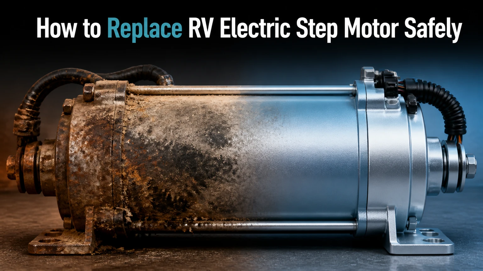
To replace an RV electric step motor, disconnect all 12-volt power, support the steps, remove the linkage pin and motor bolts, install a compatible 12-volt replacement, lubricate the mechanism, and test it from a safe position. Most accessible repairs take 30-60 minutes, but seized pins, corrosion, or a misdiagnosed controller can extend the job.
Key facts at a glance
RV electric step motors normally operate from the coach’s 12-volt DC electrical system.
Kwikee and Stromberg Carlson motors may look similar but can use different gears, mounting patterns, and linkage designs.
A motor that receives voltage but only clicks may have stripped gears, excessive mechanical load, or an internal failure.
Disconnecting the battery or step fuse is safer than relying only on the interior step switch.
A clean chassis ground and freely moving linkage protect the replacement motor from overload.
The replacement motor must match the step model, gear profile, connector, rotation, and linkage arrangement.
What Does an RV Electric Step Motor Do?
An RV electric step motor converts 12-volt electrical power into rotary movement that drives a gear and linkage assembly. The linkage changes that rotation into the outward and inward movement of the folding entry steps.
Most automatic RV steps use a door-mounted magnetic switch, a control module, a motor, a gear train, and a mechanical linkage. Depending on the design, opening the door changes the switch circuit or its ground signal, and the controller sends power to the motor with the required polarity.
The controller usually reverses motor polarity for extension and retraction. The motor does not necessarily stop through a conventional limit switch. Many Kwikee systems monitor motor current, then remove power when the mechanism reaches its travel limit and the motor load rises.
That current-sensing behavior matters during diagnosis. A brief stall at full extension can be normal. A motor that stalls halfway, runs slowly, or repeatedly cycles indicates excessive resistance, low voltage, damaged gears, or a failing motor.
How Does the Step System Operate?
The door switch provides the trigger, the controller determines direction and timing, and the motor supplies the mechanical force. A typical sequence is:
- The door changes the magnetic switch state.
- The controller detects the change.
- The controller supplies approximately 12 volts DC to the motor.
- The motor turns a worm or spur gear.
- The gear drives the step linkage.
- The controller detects the end-of-travel current increase.
- The controller cuts motor power.
The exact switch logic varies. Some systems use a normally open magnetic switch, while others use a normally closed arrangement or a switch that changes the controller’s ground path. Do not assume that a wire carrying a door signal should be connected directly to battery positive.
Which RV Step Motor Do You Need?
The correct replacement depends on the step manufacturer, series, motor generation, gear profile, connector, and mounting arrangement. Identify the step assembly and the motor label before ordering, because a motor that physically bolts on can still have the wrong gear or electrical behavior.
Kwikee, now associated with Lippert Components, has multiple generations of step motors. Older classic assemblies differ from later Integrated Motor Gear Linkage, or IMGL, designs. Stromberg Carlson and Coachstep assemblies can use different gear arrangements even when the step frames appear nearly identical.
Read the label on the motor, gearbox, or control module. Photograph the connector, mounting face, linkage arm, and gear before removal. A vehicle identification number alone is often insufficient because RV manufacturers may install different step assemblies during the same model year.
| Identification feature | Common finding | Why it matters | Verification method |
|---|---|---|---|
| Manufacturer | Kwikee, Lippert, Stromberg Carlson | Determines replacement family | Read frame or motor label |
| Motor voltage | 12 volts DC | Prevents incorrect electrical replacement | Confirm motor label and RV system |
| Gear style | 9-tooth, 11-tooth, legacy round gear | Controls mesh and travel | Count teeth or compare catalog photo |
| Connector | 2-pin or weather-sealed plug | Determines plug compatibility | Match pin count and shape |
| Mounting pattern | 3-bolt or 4-bolt housing | Determines physical fit | Measure bolt spacing |
| Linkage connection | Clevis pin, cotter pin, torque pin | Determines mechanical compatibility | Photograph the joint |
Are All Kwikee Motors Interchangeable?
No. Kwikee motors from different generations are not automatically interchangeable. A later IMGL motor may fit a Series 22, 23, 28, 32, 33, 34, 36, 38, or 40 assembly, while a pre-2006 legacy assembly can require a different gearbox and drive interface.
Catalog descriptions such as “fits Kwikee steps” are incomplete unless they list the step series or original part number. Verify the old motor number, gear count, connector, and linkage configuration against the seller’s compatibility list.
A replacement gearbox may be a better repair than a motor alone when the plastic gears are stripped. Conversely, a complete conversion kit can be more economical when the original motor and gear housing are obsolete or severely corroded.
Replacement Options and Typical Prices
Typical retail pricing ranges from $55-$140 for a motor or motor-and-gear assembly, excluding labor. Prices vary by brand, whether the gear housing is included, and whether the part is an OEM Lippert component or an aftermarket cross-reference.
| Replacement option | Typical price | Typical installation time | Best application |
|---|---|---|---|
| Legacy motor only | $55-$110 | 30-60 minutes | Older classic Kwikee assembly |
| IMGL motor and gear unit | $65-$140 | 30-60 minutes | Compatible later Kwikee series |
| Stromberg or Coachstep motor | $60-$130 | 30-75 minutes | Matching Stromberg-style linkage |
| Complete gearbox assembly | $100-$220 | 45-90 minutes | Stripped gears or damaged housing |
| Conversion kit | $130-$280 | 1-2 hours | Obsolete motor or repeated failures |
Automotive window-lift motors are sometimes cross-referenced with older RV step motors, including certain Ford Taurus applications. Treat that option as a part-number research exercise, not a universal shortcut. Connector orientation, shaft shape, gear indexing, motor rotation, and weather sealing can differ.
How Do You Confirm the Motor Is Bad?
Confirm the motor fault before removing it. A defective ground, blown fuse, failed controller, damaged door switch, seized pivot, or low battery can produce the same symptom as a dead motor.
Start with a visual inspection. Look for a disconnected green or black ground wire, rust around the frame attachment, damaged insulation, a loose plug, broken cotter pin, bent linkage, and debris packed around the pivot points.
A “thump” or click does not prove that the motor itself has failed. The controller may be energizing a motor whose internal gear is stripped, but the same sound can occur when a dry linkage has overloaded the gearbox.
Electrical Diagnosis
Use a digital multimeter set to DC volts. Keep hands away from the linkage and work from the side of the step.
- Charge the house battery or connect the RV to a stable 12-volt source.
- Locate the motor connector and separate the motor side from the controller side.
- Connect the meter probes to the controller-side motor terminals.
- Open and close the entry door while observing the meter.
- Expect a brief voltage pulse, often near battery voltage, with polarity changing between directions.
- Measure at the motor connector while the plug is connected if the design permits back-probing.
- Compare the measured voltage with battery voltage.
A momentary reading near 12 volts at the controller plug indicates that the controller and door trigger are functioning under that test condition. It does not prove that the motor receives adequate current, because a corroded connector can show voltage with no useful load capacity.
A large voltage drop under load points toward a poor ground, damaged positive lead, weak connector, fuse holder resistance, or controller contact problem. Clean and retest before condemning the motor.
Ground Testing
The chassis ground deserves its own test because paint, road salt, and frame corrosion increase resistance. Disconnect power first, remove the ground fastener, clean the terminal and bare frame metal, then reinstall the connection with corrosion protection around the joint.
For a loaded test, connect the multimeter’s negative probe to the motor ground and the positive probe to the battery negative terminal while the step attempts to move. A measurable voltage difference indicates resistance in the ground path. The exact acceptable value depends on the manufacturer, but a reading approaching 0.5 volts under load deserves correction.
Do not rely on an ohms test alone. A wire can show low resistance with no load and still fail when the motor draws several amps.
Direct Battery Test
A direct test can separate the motor from the controller, but it introduces movement risk and can damage wiring if performed carelessly.
Remove the motor connector from the vehicle harness. Use fused jumper leads from a known-good 12-volt battery, preferably with an inline fuse rated for the motor circuit. Briefly apply power to the motor terminals, then reverse the leads to test the opposite direction.
A motor that spins smoothly in both directions is probably functional, although it may still fail under mechanical load. A motor that sparks heavily, turns slowly, only clicks, or will not run with direct power is a strong replacement candidate.
Do not hold the motor stalled against the battery. Current rises rapidly when the shaft cannot turn, and the motor, jumper, or battery can overheat.
Before You Start the Replacement
Prepare the workspace before disconnecting anything. The step can move unexpectedly if power returns, the controller receives a door signal, or the motor’s mechanical restraint is released.
| Preparation item | Typical value | Required action | Failure prevented |
|---|---|---|---|
| Repair time | 30-60 minutes | Add time for seized hardware | Rushed installation |
| Difficulty | Moderate | Use side access and stable support | Crush injury or dropped motor |
| Battery state | 12.4-12.8 volts at rest | Disconnect negative or step fuse | Unexpected movement |
| Support blocks | 2 solid blocks | Support frame, not thin tread | Step collapse |
| Replacement hardware | 1 cotter pin minimum | Replace bent or rusted retainers | Linkage separation |
| Lubricant | Water-resistant lithium grease | Apply thin, complete coating | Overload and premature wear |
Tools and Materials
Gather a socket set, commonly 7/16-inch or 10 mm, Phillips and flat screwdrivers, needle-nose pliers, a wire brush, penetrating oil, a digital multimeter, a flashlight, dielectric grease, water-resistant lithium grease, replacement cotter pins, and a fused pair of jumper leads if testing is required.
Use penetrating oil only to free rusty fasteners. WD-40 can help displace water or loosen contamination, but it is not a durable gear lubricant. Use lithium grease on metal gears and pivots unless the step manufacturer specifies a different product.
Park on level ground, set the parking brake, and keep the entry door position under control. Tell anyone nearby not to operate the door or battery disconnect during the repair.
How to Replace RV Electric Step Motor
The replacement requires seven controlled actions: secure the steps, isolate power, disconnect the harness, release the linkage, remove the old motor, align the new unit, and test the completed installation. The most important success factor is matching the replacement motor to the original step assembly rather than choosing by appearance.
Step 1: Extend and Support the Steps
Extend the steps fully if the motor still operates. If the steps are stuck retracted, move them only after power is isolated and use a safe support position that cannot damage the tread or linkage.
Place solid wood blocks or rated jack stands beneath the step frame or lower support structure. Keep fingers, feet, and tools outside the linkage arc because the assembly can move when the motor gear disengages.
You will know it worked when the step assembly cannot drop, swing, or retract after the motor is removed. The common mistake is supporting the thin tread alone, which can bend the step or allow it to fall.
Step 2: Disconnect Every Power Source
Turn off the interior step switch, remove the step fuse if identified, and disconnect the 12-volt house battery negative cable or battery disconnect. If the RV has solar charging, prevent the solar controller from feeding the 12-volt bus during the repair.
Open and close the door after isolation only if you have verified that no step movement is possible. Test the motor connector with a meter or test light, then wait several minutes for controller activity to stop.
You will know it worked when the motor connector has no active supply and the step remains stationary during door movement. The common mistake is trusting the inside step switch as the only disconnect, because that switch may control automatic behavior without removing battery power.
Step 3: Photograph and Unplug the Motor Harness
Take close photographs of wire routing, connector orientation, ground location, linkage position, and mounting-bolt placement. Disconnect the weather-sealed motor plug without pulling on the wires.
Inspect the terminals for green corrosion, pushed-back pins, moisture, or heat discoloration. Apply a small amount of dielectric grease during reassembly, but do not pack the connector so heavily that the terminals cannot seat.
You will know it worked when the connector separates cleanly and each wire remains attached to its terminal. The common mistake is cutting the harness before confirming that the replacement motor uses the same connector.
Step 4: Remove the Linkage Clevis Pin
Locate the clevis pin or torque pin connecting the motor arm to the step linkage. Straighten and remove the cotter pin with needle-nose pliers, then withdraw the clevis pin while supporting the linkage by hand.
If the pin is seized, apply penetrating oil and work it gradually. Do not hammer against a thin aluminum gear plate or pry against the motor housing, because the plate can crack or deform.
You will know it worked when the step linkage is mechanically separate from the motor arm. The common mistake is removing motor bolts while the linkage remains loaded, which can make the housing twist or fall suddenly.
Step 5: Remove the Motor Mounting Bolts
Support the motor with one hand while removing the three or four mounting bolts with the correct socket. Keep washers and spacers in order, and avoid rounding fasteners with an oversized or poorly seated socket.
Once the bolts are out, pull the motor straight away from the gear plate. Slight rotation may help disengage the drive gear, but do not force the motor sideways against the linkage teeth.
You will know it worked when the old motor separates without bending the plate or damaging the gear teeth. The common mistake is allowing the motor to drop, which can pull on the harness or crack the connector.
Step 6: Inspect, Clean, and Install the Replacement
Compare the old and new units before installation. Check bolt spacing, gear profile, connector, arm position, shaft orientation, rubber bumpers, and the relationship between the motor arm and linkage.
Brush hardened grease and rust from accessible gear teeth. Apply a thin coat of water-resistant lithium grease to metal gear teeth and pivot points, but do not fill the housing with excess grease that can increase drag or collect abrasive dust.
If the new assembly lacks a removable gear, bumper, spacer, or linkage arm supplied with the old unit, transfer only the components identified by the replacement instructions. Some motors arrive as complete integrated units and should not be opened.
Seat the replacement motor flush against the gear plate. Start every bolt by hand, align the teeth without forcing them, and tighten evenly. Use the manufacturer’s torque specification when available, especially where bolts thread into aluminum.
You will know it worked when the mounting faces meet evenly, the gear teeth mesh without binding, and the linkage arm matches the photographs taken before removal. The common mistake is mounting the arm 180 degrees out of position.
Step 7: Reconnect the Linkage and Test
Install the clevis pin through the correct linkage holes and secure it with a new cotter pin. Reconnect the motor plug, inspect the ground connection, and ensure no wire can contact the moving step.
Stand beside the RV, not beneath the step. Restore the battery or fuse, keep hands clear, and operate the door through several complete cycles. Listen for smooth movement, full extension, firm retraction, and controller shutoff at both limits.
You will know it worked when the steps complete five consecutive cycles without hesitation, unusual clicking, partial travel, or repeated motor running. The common mistake is testing with body parts under the mechanism because the first cycle appears predictable.
What If the Steps Are Stuck Extended?
Leave stuck-extended steps supported and secure them for travel rather than forcing the motor to operate. Disconnect power, inspect the linkage, and determine whether the obstruction is mechanical or electrical before removing the motor.
For a temporary travel arrangement, use a manufacturer-approved retaining method or a secure mechanical strap that cannot enter the gear path. Do not tie the steps to a thin body panel or rely on a loose bungee cord near moving hardware.
If the steps are retracted, avoid crawling beneath them to release the motor. Use a service position that gives your hands side access, and obtain professional assistance when rusted hardware prevents safe support.
Common Mistakes and How to Fix Them
| Mistake | Observable symptom | Likely cause | Corrective action |
|---|---|---|---|
| Wrong motor family | Motor bolts on but steps bind | Gear or rotation mismatch | Match series and original part number |
| Power left connected | Step moves unexpectedly | Controller receives door signal | Remove fuse and battery negative |
| Ground ignored | Motor clicks or runs weakly | Corroded frame connection | Clean ground and perform loaded test |
| Dry linkage retained | New motor overheats | Excessive pivot resistance | Clean and lubricate pivots |
| Old cotter pin reused | Pin backs out during travel | Rust or distorted legs | Install a new cotter pin |
| Gear forced into mesh | Noise and incomplete travel | Incorrect arm orientation | Recheck photographs and timing |
A replacement motor cannot overcome a bent step frame indefinitely. If the step binds when moved manually with power disconnected, repair the hinge, pivot, obstruction, or alignment problem before installing another motor.
A second practitioner rule is to compare motor voltage during movement, not only battery voltage at rest. A battery may read 12.6 volts unloaded and fall below the controller’s reliable operating range when the motor demands current.
A third rule is to treat repeated motor failure as a load problem until proven otherwise. Replacing motors without correcting rust, dry pivots, damaged gears, or low voltage often produces the same failure within weeks.
How Should You Lubricate RV Electric Steps?
Lubricate the step pivots, hinge points, and accessible gear teeth with a small amount of water-resistant lithium grease after cleaning. Do not use thin penetrating spray as the primary long-term lubricant, and do not coat electrical connectors with ordinary grease.
Move the steps manually with power disconnected to expose the pivot surfaces. Wipe away contaminated grease, brush off rust flakes, and apply enough grease to form a thin continuous film. Excess lubricant attracts road grit and can turn into abrasive paste.
Lubrication does not repair stripped gears or a worn bushing. If a pivot remains tight after cleaning, identify the binding component instead of increasing grease volume.
When Should You Replace the Gearbox Instead?
Replace the complete gearbox or motor-and-gear assembly when the plastic gears are stripped, the housing is cracked, the output shaft is loose, or the replacement motor does not include a compatible drive gear. A motor-only replacement is appropriate when the gear train and linkage are sound.
| Condition | Motor-only repair | Complete assembly | Recommended decision |
|---|---|---|---|
| Motor open circuit | Appropriate | Optional | Replace motor if gear teeth are sound |
| Stripped plastic gear | Insufficient | Appropriate | Replace gearbox or integrated unit |
| Cracked gear housing | Insufficient | Appropriate | Replace complete gearbox |
| Bent linkage plate | Insufficient | Insufficient alone | Repair or replace step assembly |
| Dry but undamaged pivots | Appropriate | Unnecessary | Clean and lubricate first |
| Corroded connector | Conditional | Conditional | Repair wiring before parts purchase |
What Are the Alternatives to a Direct Motor Replacement?
A direct replacement is the safest choice when the original step model remains supported and the frame is structurally sound. A complete gearbox, conversion kit, or automotive cross-reference can reduce cost, but each alternative introduces compatibility checks.
A complete integrated motor-and-gear unit reduces the chance of mismatched internal components. It usually costs more than a bare motor but can save labor when the original gear case has wear.
A conversion kit makes sense when an obsolete legacy motor is difficult to source or when the step has repeated gear failures. Confirm whether the kit supports a single or double linkage and whether it changes the controller or wiring.
An automotive window motor can be inexpensive, but it is not automatically weatherproof for an RV underbody. Use it only when the shaft, gear, rotation, mounting pattern, connector, and current characteristics have been independently verified.
How Much Does RV Step Motor Replacement Cost?
A DIY motor replacement typically costs $55-$140 for the part and takes 30-60 minutes when the fasteners and linkage pin release normally. A professional repair commonly adds approximately $100-$250 in labor, with higher totals for complete assemblies, wiring repairs, or seized hardware.
| Repair scenario | Parts range | Labor time | Typical total before tax |
|---|---|---|---|
| Motor-only DIY repair | $55-$140 | 30-60 minutes | $55-$160 |
| Motor replacement by shop | $55-$140 | 1-2 hours | $155-$390 |
| Gearbox replacement | $100-$220 | 1-2 hours | $200-$470 |
| Conversion kit installation | $130-$280 | 1-2 hours | $230-$530 |
| Wiring or ground repair | $10-$75 | 30-120 minutes | $10-$325 |
These are typical planning ranges, not a quoted repair price. Access, regional labor rates, shipping, corrosion, and the exact Lippert or Stromberg assembly affect the final amount.
When Should You Use a Professional?
Use a qualified RV technician when the step frame is bent, the assembly cannot be safely supported, the wiring has melted, the controller repeatedly cycles, or the motor area is inaccessible without removing body panels. A professional is also appropriate when you cannot positively identify the step model.
Stop the repair if a mounting bolt breaks in the gear plate, the linkage remains loaded, or the step moves while power is supposedly disconnected. The risk is greater than the value of saving a short labor charge.
Frequently Asked Questions
Can I Manually Use RV Steps With a Bad Motor?
You can manually position some RV steps after disconnecting power, but the method depends on the linkage and gearbox design. Support the steps, avoid forcing the gear train, and secure the assembly for travel. Never allow a partially supported step to carry a person until the retaining method and structural condition are verified.
Why Does My RV Step Work Only When the Engine Runs?
An engine-running condition often indicates low house-battery voltage, a weak ground, a failing battery disconnect, or excessive resistance in the positive cable. Measure voltage at the motor while the step moves, then compare it with chassis or house-battery voltage. The alternator may temporarily mask a poor battery or connection.
Can a Bad Door Switch Damage the Step Motor?
A bad door switch usually prevents activation or causes intermittent operation, rather than directly damaging the motor. A switch that chatters can make the controller cycle repeatedly, increasing wear and heat. Inspect switch alignment, magnet position, wiring continuity, and controller behavior before replacing the motor.
How Often Should Automatic RV Steps Be Lubricated?
Inspect and lubricate RV step pivots at least twice per camping season and after exposure to heavy rain, road salt, dust, or beach sand. Lubricate sooner when movement becomes slower or noisier. Cleaning matters more than adding grease over contaminated deposits.
Should the Step Motor Run Until It Stops?
The motor may run briefly into a full-extension or full-retraction stop while the controller detects increased current and cuts power. Continuous running, repeated clicking, halfway stopping, or overheating is abnormal. Those symptoms indicate excessive resistance, incorrect gear timing, low voltage, or controller failure.
Is an RV Step Motor Covered by the RV Warranty?
Coverage depends on the RV manufacturer warranty, the step manufacturer’s warranty, purchase date, and whether the failure resulted from damage or lack of maintenance. Record the step model, motor part number, photographs, and diagnostic results before submitting a claim. A warranty provider may require an authorized repair.
The Bottom Line
Replacing an RV electric step motor is usually a 30-60 minute repair when the motor is correctly identified, the steps are supported, and the linkage is free. Diagnose voltage, ground quality, mechanical binding, and gear damage first, because a new motor cannot compensate for a corroded connection or overloaded step.
Use the original model and part number to select the replacement, disconnect every 12-volt source, photograph the original orientation, install a new cotter pin, lubricate the mechanism, and test from the side. Those controls make how to replace rv electric step motor a manageable repair rather than a repeat failure or crushing hazard.