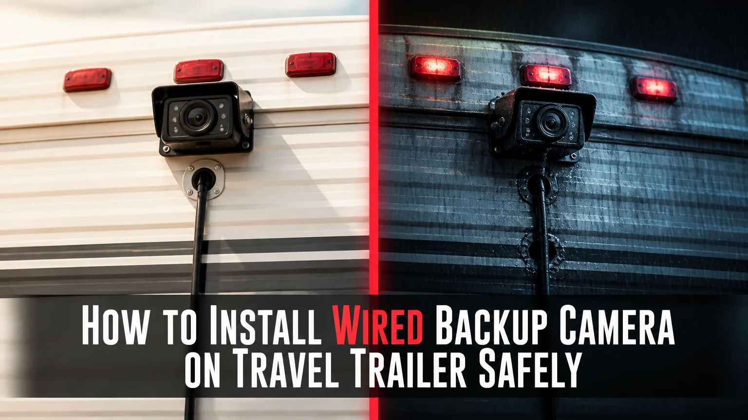
To install a wired backup camera on a travel trailer, mount the camera high and centered, run protected video and power cable to a weatherproof tongue connector, route a matching truck cable into the cab, and connect a fused 12-volt monitor. Plan 3-6 hours, and verify the manufacturer’s pinout before applying power.
Key Facts
A wired trailer camera needs a camera, trailer cable, hitch umbilical, truck cable, monitor, and protected 12-volt power source.
A typical DIY installation costs $150-$450 for parts and takes 3-6 hours.
A 4-pin aviation connector is not automatically compatible with every other 4-pin connector; pin assignments must match.
The hitch cable needs enough slack for the tightest expected turn without dragging, stretching, or touching the ground.
Camera cable should remain separated from exhaust components, suspension travel, sharp edges, and exposed road debris.
The monitor can display continuously when ignition-switched or activate only when the tow vehicle is in reverse.
What parts does a wired trailer camera system need?
A wired travel-trailer camera system has six functional parts: the rear camera, trailer-side cable, trailer tongue connector, coiled tow-vehicle umbilical, cab-side cable, and monitor. Power may reach the camera through the video cable, through a separate trailer circuit, or through a dedicated fused lead, depending on the kit design.
| Component | Typical specification | Installation requirement |
|---|---|---|
| Rear camera | 12 V DC, 120-150° view, IP66-IP69K | Centered mount with sealed cable entry |
| Trailer cable | 15-40 ft, 4-6 conductors | Loom or enclosed channel under the trailer |
| Hitch umbilical | 3-6 ft coiled, locking connector | Slack for articulation and strain relief |
| Monitor | 5-9 in, 12 V DC, CVBS or AHD input | Dash, mirror, or overhead mounting |
| Fuse protection | 1-5 A, kit-dependent | Fused positive lead near power source |
| Sealant and fasteners | RV sealant, stainless screws | Seal every exterior penetration |
The connector format does not establish compatibility. Two products can both use a four-pin aviation plug while assigning power, ground, video, and audio to different pins. Compare the wiring diagram printed on the camera, monitor, or manufacturer’s manual before connecting the system.
Which camera and monitor specifications matter?
Choose a camera rated for exterior vehicle use, a monitor that accepts the camera’s signal type, and a cable long enough to avoid stretched connections. A 1080p AHD camera does not produce a 1080p image on a CVBS-only monitor, and a high-resolution monitor cannot restore detail lost by a composite camera.
| System type | Video resolution | Typical kit price | Best use |
|---|---|---|---|
| CVBS wired kit | Approximately 480p | $80-$160 | Budget installation and short trailers |
| AHD 720p kit | 720p | $120-$250 | General highway and campsite visibility |
| AHD 1080p kit | 1080p | $150-$350 | Long trailers and detailed daytime views |
| Mirror monitor kit | 5-7 in display | $120-$300 | Factory-looking truck interior |
| Dash monitor kit | 5-9 in display | $100-$400 | Multiple cameras and adjustable viewing |
A wide viewing angle increases side visibility but can make distant objects appear smaller. For a single rear camera, approximately 120-140 degrees is often easier to interpret than an extreme fisheye lens, especially when judging the distance to a post or vehicle.
How does a wired backup camera work on a travel trailer?
A wired backup camera sends video through a physical cable between the trailer and tow vehicle, avoiding radio interference and reducing transmission delay. The rear camera captures the image, the trailer cable carries the signal toward the tongue, the coiled umbilical crosses the hitch gap, and the truck cable delivers the signal to the monitor.
The camera may receive 12-volt power from the trailer’s lighting circuit, a dedicated fused circuit, or the monitor harness. The monitor usually needs its own ignition-switched positive lead and a clean ground. A reverse-trigger wire can activate the display only in reverse, but continuous viewing is often more useful for lane changes and traffic monitoring.
A wired system is resistant to wireless signal congestion, but it is not maintenance-free. Water, corrosion, crushed insulation, poor grounding, voltage drop, and a damaged hitch cable can still produce a black or unstable image.
Can the camera use the trailer’s 7-way connector?
A camera system can use the tow vehicle’s 7-way connector for power only when the camera manufacturer explicitly supports that arrangement. The standard 7-way trailer connector commonly provides an auxiliary 12-volt circuit, but its pin assignment, vehicle fuse status, and power availability must be verified with the tow vehicle manufacturer’s wiring diagram and a multimeter.
Do not assume that the 7-way connector carries video. It normally does not. A dedicated video umbilical or a manufacturer-approved adapter is required for a wired camera signal.
What should you do before drilling or wiring?
Before installation, bench-test the complete camera, monitor, and cable assembly, then map the cable route and identify every power source. Disconnect the trailer battery, tow vehicle battery, and any shore-power connection before cutting or terminating wires, unless the manufacturer’s test procedure specifically requires a controlled powered test.
Before You Start
| Item | Typical requirement | Check before work |
|---|---|---|
| Installation time | 3-6 hours DIY | Add a second day for concealed interior routing |
| Difficulty | Moderate electrical and mechanical work | Use a shop if structural framing is uncertain |
| Camera position | High, centered, 6-12 in below roof edge | Avoid roof seal transitions and marker-light wiring |
| Cable slack | 24-36 in at tongue, kit-dependent | Confirm full-lock turning clearance |
| Tools | Drill, bits, multimeter, crimper, trim tools | Add a fish tape for interior routing |
| Materials | Loom, P-clamps, sealant, heat-shrink | Use UV-rated external hardware |
Lay every cable on the ground in its intended order. Connect the system to a regulated 12-volt source, not an unknown battery charger, and check the picture in daylight and darkness. Photograph the working pinout and label both ends of each cable.
The most valuable practitioner rule is simple: never bury a cable that has not passed a complete bench test. Removing underbelly panels is slow; removing sealed camera hardware is slower.
How to install a wired backup camera on a travel trailer
The installation has six main stages: plan the route, mount and seal the camera, route the trailer cable, install the tongue connector, route the truck cable and power, then calibrate the complete system. The most important success factor is mechanical protection at the hitch, where repeated articulation creates more stress than the straight cable runs.
Step 1: Map and test the complete cable route
Place the camera at the proposed rear location, route the trailer cable toward the tongue, position the coiled umbilical across the hitch, and mock up the truck cable to the monitor. Leave extra length for bends, service loops, and suspension movement rather than measuring only the straight-line distance.
Use a multimeter to identify positive, ground, and trigger circuits. Confirm continuity from each connector pin to its intended terminal, then compare the result with the kit diagram. Never use wire color as the only identification method because aftermarket harness colors vary.
You will know it worked when: the monitor shows a stable image while the cables remain in their planned positions.
Common mistake: ordering a cable that reaches the parked vehicles but becomes tight when the trailer turns.
Step 2: Mount the camera high, centered, and level
Mark the horizontal centerline on the trailer’s rear wall and choose a position high enough to see the hitch, rear corners, and road behind the trailer. A position roughly 6-12 inches below the roof edge often works, but roof curvature, ladders, spare tires, clearance lamps, and manufacturer framing should determine the final location.
Check inside the wall before drilling. Do not cut through structural framing, factory wiring, plumbing, or a laminated wall without confirming the construction. Drill the cable hole using the diameter specified by the camera manufacturer, commonly 5/8 inch for a grommeted harness, then deburr the opening and protect the cable from the edge.
Apply compatible RV sealant around the cable entry and behind the mounting bracket. Products such as Dicor or Geocel Pro Flex are commonly used on RV exteriors, but the sealant must be compatible with the trailer’s fiberglass, aluminum, painted surface, and camera housing.
Fasten the bracket with stainless screws into framing when available. If the manufacturer permits a skin mount, use the supplied fasteners and avoid overtightening, which can deform the wall or crack fiberglass.
You will know it worked when: the bracket is rigid, the lens is level, and no exposed gap surrounds the cable entry.
Common mistake: sealing only around the outside of the hole while leaving the cable able to wick water into the wall.
Step 3: Route and protect the trailer cable
Route the trailer cable inside cabinetry when access is practical and the cable can remain dry. Use the underbelly or frame path when interior furniture, tanks, insulation, or laminated walls make concealed routing disruptive.
Keep external cable at least several inches from exhaust pipes and away from brake assemblies, suspension travel, stabilizer jacks, slide mechanisms, and sharp frame edges. Place the cable inside split loom where gravel, road salt, or ultraviolet exposure can damage insulation.
Secure the loom with rubber-lined P-clamps or UV-resistant cable ties at approximately 18-24-inch intervals. Add an abrasion sleeve at every frame pass-through. Do not let cable ties carry the cable across a sharp flange; the tie can hold the wire in the exact position where vibration cuts it.
Maintain gradual bends. Do not fold a coaxial or multi-conductor cable into a tight radius near a connector.
You will know it worked when: the cable cannot sag into moving parts, rub against metal, or contact a hot component during travel.
Common mistake: fastening the cable to a brake line or suspension component because it appears convenient.
Step 4: Install the trailer tongue connector and coiled umbilical
Mount the trailer-side socket on a rigid, protected surface near the tongue, with the connector opening directed downward or capped when disconnected. Leave approximately 24-36 inches of service slack between the final frame attachment and the socket, unless the kit specifies another length.
Install strain relief on both sides of the connector. The socket should not carry the cable’s hanging weight, and the coiled umbilical should not pull sideways on the connector during a turn. Keep the connector above likely splash and scrape zones.
Connect the tow vehicle and trailer on level ground. Turn the trailer as far as practical in both directions while an observer watches the umbilical. Repeat the check with the tongue jack, safety chains, and weight-distribution hardware in their normal positions.
You will know it worked when: the coil remains connected and clear of the ground at the tightest tested angle.
Common mistake: leaving only a straight, taut span between the socket and the first clamp. That arrangement can tear the cable during a sharp backing maneuver.
Step 5: Route the truck cable and connect monitor power
Route the truck cable through an existing rubber body grommet whenever possible. If a new opening is unavoidable, install a proper grommet and seal its perimeter; never allow a cable to pass directly through a drilled metal hole.
Tuck the cable behind trim panels without crushing it under clips or seat tracks. Keep the video cable separated from high-current wiring for inverters, amplifiers, and electric seat motors when practical. Electrical noise is less common with a properly designed kit, but poor routing and poor grounding can still create rolling lines.
Connect monitor power through an ignition-switched fuse using an appropriately rated add-a-circuit, if the vehicle manufacturer permits that installation. Use the fuse rating specified by the camera kit, commonly 1-5 amps, and place protection close to the power source. Do not install a larger fuse to cure a nuisance opening.
Connect the monitor ground to a verified ground point or the manufacturer’s designated ground circuit. A painted bolt is not automatically a good ground. Clean the contact surface and confirm low resistance with a multimeter.
Use the reverse trigger only if reverse-only operation is wanted. If the monitor requires a reverse signal, connect the trigger to the tow vehicle’s verified reverse-light circuit according to its wiring diagram, not by guessing from wire color.
You will know it worked when: the monitor starts with ignition power, the image remains stable with headlights and accessories operating, and the fuse stays cool.
Common mistake: powering a monitor from an unfused accessory wire or a constant circuit that can drain the truck battery.
Step 6: Seal, calibrate, and test under real conditions
Reconnect power and test the system while the trailer is stationary. Select the correct monitor input, confirm the camera image is upright, and adjust the bracket so the lower part of the image includes the trailer bumper or hitch area without filling most of the screen.
Test the camera in daylight, at night, and with the trailer lights operating. Walk a person or place a large object at known distances, such as 10, 20, and 30 feet, to learn how the lens represents distance. A camera view is an aid, not a substitute for mirrors, a spotter, or physically checking the campsite.
Spray water over the camera entry and inspect the interior side after drying. Do not use a pressure washer directly against a seal that has not cured for the sealant’s stated period. Recheck clamps and connector collars after the first trip.
You will know it worked when: the image remains stable during ignition cycling, lighting changes, tight turns, and a short road test.
Common mistake: adjusting the camera only while parked straight, then discovering that the hitch cable or camera view fails during articulation.
How much do parts and installation typically cost?
A typical wired travel-trailer camera installation costs $150-$450 for a single-camera DIY system, excluding a new monitor or unusual wall repairs. Labor commonly adds $150-$500, with concealed interior routing and difficult underbelly access producing the largest price increase.
| Installation scope | Parts range | DIY time | Typical shop labor |
|---|---|---|---|
| Existing route, CVBS kit | $80-$180 | 2-3 hours | $150-$250 |
| External frame route, AHD kit | $150-$350 | 3-5 hours | $250-$450 |
| Concealed interior route | $180-$450 | 5-8 hours | $400-$700 |
| Rear plus side cameras | $300-$900 | 6-10 hours | $600-$1,200 |
Prices vary with cable length, monitor type, connector quality, wall construction, and whether the tow vehicle already has a suitable display. A professional installation becomes more economical when removing cabinets, ceiling panels, or sealed underbelly material would create secondary repair work.
Is wired better than wireless for a travel trailer?
Wired systems are usually better for long trailers, frequent highway travel, and owners who prioritize a consistent image over installation speed. Wireless systems are better when the camera must move between vehicles, drilling is unacceptable, or the trailer is short enough for the radio link to remain dependable.
| Decision factor | Wired system | Wireless system |
|---|---|---|
| Typical installation | 3-8 hours, cable routing required | 30-90 minutes, camera and transmitter mounting |
| Video delay | Usually very low | Often measurable, kit-dependent |
| Interference risk | Cable damage and electrical noise | Radio congestion and signal obstruction |
| Hitch maintenance | Coiled cable and connectors | No video umbilical |
| Vehicle flexibility | Cable-specific installation | Easier to move between tow vehicles |
| Long-trailer suitability | Strong, with correct cable length | More dependent on antenna placement |
| Typical single-camera cost | $150-$450 | $100-$350 |
A wired system is not automatically “zero latency” or “interference-free.” The physical link avoids radio interference, but digital processing still creates some delay, and electrical noise or a damaged conductor can affect the image. That distinction matters when comparing advertising claims with actual operation.
When is wireless a better choice?
Wireless is a reasonable choice for occasional users with a short travel trailer, a removable camera mount, or a tow vehicle that changes frequently. Wireless becomes less attractive when the trailer has a metal rear wall, the transmitter is far from the receiver, or the driver needs continuous lane-monitoring video at highway speed.
What are the best installation variations?
The best route depends on trailer construction, length, and how often the camera will be removed. Interior routing protects the cable better, while external frame routing reduces disassembly and makes future inspection easier.
Long trailers over 30 feet
Use a cable length that leaves service loops at both ends rather than connecting multiple unapproved extensions. Test the image before fastening the entire run because voltage drop, incompatible connectors, and poor shielding become more noticeable over long routes.
Trailers with enclosed underbellies
If the underbelly is sealed, route through accessible service channels or use a qualified RV technician rather than cutting large openings without a resealing plan. Any opening must be patched with material compatible with the underbelly membrane and protected from water flow.
Trailers with a rear ladder or spare tire
Mount the camera where the ladder or tire cannot block the viewing cone. A high camera may see over a spare tire but still produce a blind zone immediately behind it, so test the lower field of view with a person outside the trailer.
Detachable or frequently changed tow vehicles
Use a trailer-side socket and a replaceable truck-side cable instead of routing a permanent cable through the hitch structure. Label the connector and keep a capped spare cable in the tow vehicle because hitch-side damage is more likely than failure in the protected monitor harness.
What are the most common wired camera failures?
Most wired camera failures result from connector mismatch, bad grounds, water entry, damaged hitch cables, or incorrect monitor input selection. Diagnose the system from the monitor backward, testing power, ground, signal continuity, and physical damage in that order.
| Symptom | Likely cause | First test | Corrective action |
|---|---|---|---|
| Black screen | Wrong input or no camera power | Measure camera voltage | Select input, repair fuse or power lead |
| No image after turning | Stretched umbilical | Inspect coil at full lock | Add slack and reposition clamps |
| Flickering lines | Ground noise or damaged cable | Test with temporary clean power | Improve ground or replace cable |
| Purple or green image | Signal mismatch or camera fault | Confirm CVBS/AHD compatibility | Change monitor input or replace camera |
| Fogged lens | Water inside housing | Inspect seals after drying | Replace camera if housing leaks |
| Intermittent image | Corroded connector pin | Wiggle-test each connector | Clean or replace connector and cap |
A black screen with a powered monitor does not prove camera failure. Check whether the monitor is on the correct AV channel, then verify camera voltage under load. A no-load voltage reading can appear normal even when a corroded connector collapses the supply once the camera is connected.
Do not strike a camera housing to reset an infrared filter. If the image has a persistent purple or green tint, verify signal compatibility, power quality, and camera failure according to the manufacturer’s service procedure; replace the unit when the sealed housing or sensor is defective.
What safety and legal issues should you check?
A trailer camera should supplement, not replace, required mirrors, lighting, brake equipment, or a spotter. Check local vehicle-equipment rules before using a monitor as a substitute for a required rear-view mirror, and confirm that the camera mount does not obscure identification lamps or required reflectors.
Disconnect power before cutting trailer wiring. Protect every positive lead with a fuse, support cables independently of brake lines, and keep wiring clear of heat and moving components. If the trailer uses electric brakes, do not splice into the brake controller circuit for camera power.
A shop should handle the work when the trailer has a bonded laminated wall, inaccessible structural framing, complex multiplex wiring, a sealed underbelly that cannot be resealed confidently, or a tow vehicle under warranty with restricted wiring modifications. The camera itself is low voltage, but careless routing can affect braking, lighting, water resistance, or fire protection.
FAQ
Can I install a wired camera without removing the trailer underbelly?
Yes, many installations can use interior cabinetry, existing wire channels, or an external frame route. Avoid opening a sealed underbelly unless the route is otherwise impossible, because a poorly patched membrane can admit water and road debris. External loom and P-clamps are acceptable when the cable remains clear of heat, suspension, and abrasion.
Should a travel-trailer camera stay on while driving?
A continuously powered camera is useful for lane changes, traffic checks, and monitoring a following vehicle. A reverse-triggered camera is adequate for campsite backing but provides no rear view during forward travel. Use ignition-switched power when continuous viewing is desired, and follow the monitor manufacturer’s power and overheating limits.
How high should a trailer backup camera be mounted?
Mount the camera as high and close to the centerline as the trailer structure allows, commonly 6-12 inches below the roof edge. The final height must avoid roof seams, framing conflicts, marker-light wiring, ladders, and spare tires. Include the trailer bumper in the image so the driver can judge backing distance.
Can I extend a camera cable with any four-pin aviation cable?
No. Four-pin aviation connectors do not guarantee identical pin assignments, signal type, shielding, or voltage capacity. Use the extension specified by the camera manufacturer, or verify every conductor against both wiring diagrams before connecting. An apparently matching plug can send supply voltage into a video input and damage equipment.
Why does the camera work on the bench but fail on the trailer?
A bench test uses short cables and stable power, while the installed system adds voltage drop, connector exposure, cable movement, and vehicle electrical noise. Test voltage at the camera with the system operating, inspect the hitch connection at full turn, and check the ground at the actual installation point rather than at the workbench.
Is a trailer camera worth installing for a weekend camper?
A wired camera is worthwhile when the trailer has poor rear visibility, frequent campsite backing, or a length that makes wireless performance uncertain. A single CVBS or 720p AHD kit with a 5-7-inch monitor usually provides adequate maneuvering information without the cost and labor of a multi-camera system.
The Bottom Line
To install a wired backup camera on a travel trailer, bench-test the matched components, mount the camera high and centered, seal the wall penetration, protect the trailer cable, and test the coiled umbilical at full hitch articulation. Use fused 12-volt power, verify the connector pinout, and choose wired equipment when dependable long-trailer visibility matters more than quick installation.