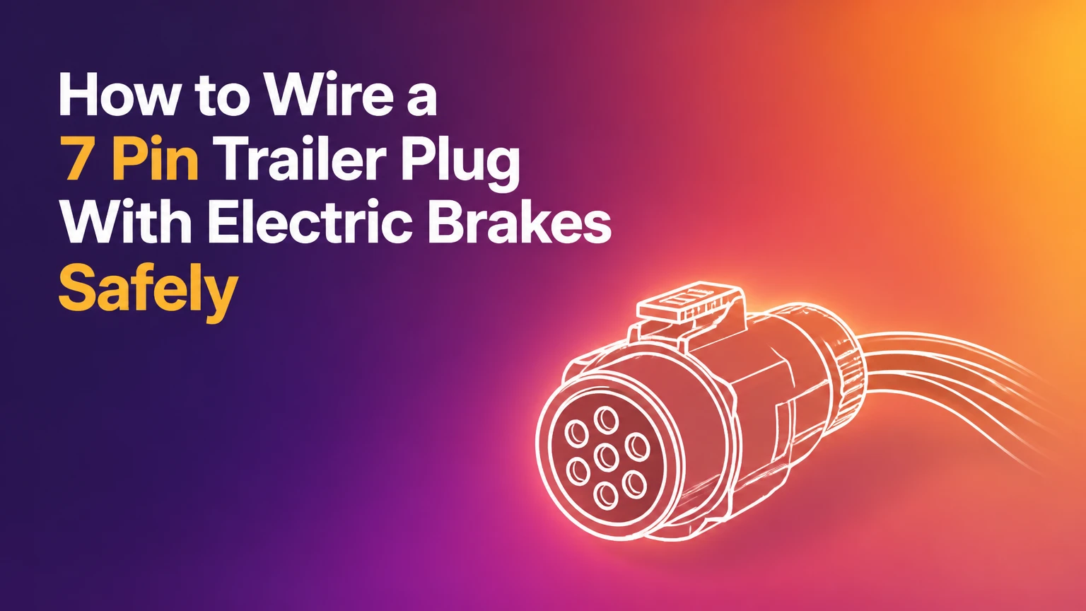
To wire a 7-pin trailer plug with electric brakes, connect the North American RV blade terminals to ground, lighting, reverse, auxiliary 12-volt power, and brake-controller output according to the molded terminal labels. Use a junction box or sealed connectors, ground the brake system reliably, then test every circuit with a multimeter before towing.
Key Facts at a Glance
The blue wire normally carries variable output from the in-cab brake controller to the trailer brake magnets.
A seven-way RV blade connector is not the same standard as a European 7-pin 12N connector.
Wire colors vary, so the terminal function stamped inside the plug takes priority over color.
Electric brake magnets typically draw about 3-4 amps each at full application.
A white ground wire should connect to a clean frame ground and to dedicated brake grounds where practical.
A multimeter, test light, and manual brake-controller override can identify most wiring faults before road testing.
What does each 7-way trailer wire do?
A North American 7-way RV blade connector normally carries four lighting functions, a ground return, an electric-brake feed, and an auxiliary 12-volt circuit. The common color convention is white for ground, black for auxiliary power, blue for brakes, brown for running lights, red for left stop/turn, green for right stop/turn, and yellow for reverse.
The connector is viewed differently depending on whether you are looking into the vehicle socket, at the face of a trailer plug, or at the terminal side during assembly. That difference makes clock-position diagrams risky. Use the function labels molded into the plug body, then verify each circuit with a meter.
| Circuit function | Common wire color | Typical conductor size | What the circuit powers |
|---|---|---|---|
| Ground return | White | 10-12 AWG | Trailer frame, lamps, brake-magnet returns |
| Auxiliary 12 volts | Black, sometimes red | 10-12 AWG | Breakaway battery charging or accessories |
| Electric brakes | Blue | 10-12 AWG | Trailer brake magnets |
| Tail and marker lights | Brown | 14-16 AWG | Running, license-plate, and clearance lamps |
| Left stop and turn | Red, sometimes yellow | 14-16 AWG | Left brake and indicator lamps |
| Right stop and turn | Green | 14-16 AWG | Right brake and indicator lamps |
| Reverse lights | Yellow, sometimes purple | 14-16 AWG | Backup lamps or camera trigger |
The table shows a common RV-standard convention, not a universal color law. A replacement plug from a different manufacturer may reverse lighting colors or use red for auxiliary power. Terminal identification is authoritative.
How do electric trailer brakes receive power?
An electronic brake controller sends a controlled voltage through the brake circuit when the tow vehicle slows. The blue conductor carries that output to both brake assemblies, where electromagnets contact the rotating drum and activate the mechanical brake shoes.
Brake magnets on a tandem-axle trailer are wired in parallel. Each magnet receives the same brake-circuit voltage, while each return path must reach the ground circuit with low resistance. A controller warning such as “NC” or “not connected” usually indicates an open blue circuit, a poor ground, a damaged connector, or a disconnected magnet.
Electric brakes do not receive useful control power from the vehicle’s brake-light wire alone. The brake-light signal may tell a controller that braking has begun, but the controller must regulate the separate blue output circuit.
Which seven-way connector should you use?
The North American RV blade connector is the appropriate choice for most recreational trailers equipped with electric brakes. European 12N seven-pin connectors and many commercial round-pin connectors use different layouts, so matching the pin count does not guarantee compatibility.
| Connector type | Typical region or use | Electric-brake provision | Typical construction | Main limitation |
|---|---|---|---|---|
| RV blade 7-way | USA and Canada recreational towing | Dedicated brake terminal | Molded plastic or metal shell | Terminal orientation varies by viewing angle |
| Commercial round-pin 7-way | Heavy trucks, agricultural trailers | Configuration-dependent | Cast metal body | Pin functions are not interchangeable with RV blade |
| European 12N, ISO 1724 | UK and much of Europe | No native dedicated brake-output terminal | Small round plastic connector | Uses circuits for fog and parking-light functions |
| European 13-pin, ISO 11446 | Modern European caravans | Vehicle-specific or supplemental system | Large keyed round connector | Requires the matching vehicle standard |
| Molded RV blade cable | Replacement and new trailer wiring | Yes, if correctly terminated | Factory-sealed cable and plug | Damaged plug usually means replacing the assembly |
A European 12N plug is not a direct substitute for a North American RV blade connector when the trailer uses conventional electric drum brakes. A vehicle using a European wiring architecture may require a manufacturer-approved brake interface, an additional connector, or a dedicated wireless brake system.
Should you use a junction box or a molded cable?
A molded cable reduces termination errors at the plug, while a junction box makes future circuit repairs easier. For a new trailer or a complete replacement, a sealed molded seven-way cable entering a weatherproof junction box is usually the most reliable DIY arrangement.
| Installation method | Typical material cost | Installation time | Serviceability | Best application |
|---|---|---|---|---|
| Molded cable to junction box | $30-$75 | 1-2 hours | High at trailer circuits | New installation or full rewiring |
| Screw-terminal plug only | $15-$35 | 45-90 minutes | High at plug | Temporary repair or accessible tongue |
| Sealed butt connectors | $20-$50 | 1-2 hours | Moderate | Repairs without a junction box |
| Professional harness installation | $150-$400 | 1-3 hours | Depends on installer | Factory tow module or complex vehicle |
Dielectric grease protects connector surfaces from moisture, but it does not repair a loose terminal or substitute for a sound crimp. Apply a thin coating after the electrical connection is mechanically secure.
What should you prepare before wiring?
Plan 1-2.5 hours for a careful replacement and $30-$75 for a plug, cable, connectors, and basic protection. The job requires safe access to the trailer tongue, a compatible vehicle socket, a functioning brake controller, and enough cable length to avoid strain during turns.
Before You Start
| Requirement | Typical specification |
|---|---|
| Difficulty | Moderate, electrical and mechanical |
| Main cable | 7-conductor trailer cable, usually 10-16 AWG |
| Brake and ground conductors | 10-12 AWG for many tandem trailers |
| Lighting conductors | 14-16 AWG |
| Connectors | Adhesive-lined heat-shrink butt connectors or junction-box terminals |
| Testing tools | Digital multimeter, 12-volt test light, wire stripper, crimper |
| Protection | Split loom, cable clamps, dielectric grease, inline fuse or breaker |
| Safety condition | Vehicle ignition off, batteries disconnected during termination |
Confirm the tow vehicle’s factory wiring before cutting anything. Modern vehicles may use a body control module or tow module that requires a dedicated harness; splicing directly into LED lamp wires can create error messages or disable trailer functions.
Disconnect the negative terminal of the vehicle battery and isolate any trailer battery before stripping conductors. Do not work beneath a trailer supported only by a jack.
How to wire a 7 pin trailer plug with electric brakes
The wiring process has eight stages: identify the connector, route the cable, establish ground, connect lighting, connect brake output, protect auxiliary power, seal the assembly, and test every circuit. Terminal identification and ground quality determine success more than the order of the lighting wires.
Step 1: Identify the connector terminals
Remove the plug cover and locate the terminal labels stamped beside the screws or blades. Record the label, intended function, and actual wire color before loosening any conductor.
Do not copy a clock-position diagram without confirming its viewing direction. A plug face viewed from the mating side appears mirrored relative to the terminal side.
Success checkpoint: Every terminal has a readable function marking or a verified circuit identity.
Common mistake: Treating a plug face diagram as though it shows the rear wiring side.
Step 2: Route and strip the trailer cable
Slide the cable through the plug’s rear boot, cap, and strain-relief components before making any connections. Strip about 50 mm, or 2 inches, of the outer jacket, then remove only enough insulation to fit each terminal, usually 10-12 mm.
Leave a gentle service loop inside the plug. The cable should enter straight and be clamped by the strain relief rather than held by the individual copper conductors.
Success checkpoint: The cover and strain relief can close without pinching wires.
Common mistake: Connecting the wires first and discovering that the boot cannot slide over the cable.
Step 3: Establish the main ground
Connect the white ground conductor to the plug’s ground terminal and to a clean, bare-metal frame point using a properly crimped ring terminal. Protect the finished frame connection with corrosion-resistant hardware and sealant suitable for the trailer environment.
Do not rely on the hitch ball, coupler, safety chains, or painted frame as the electrical return. Run dedicated ground conductors to lighting assemblies and brake magnets when the trailer frame is aluminum, heavily painted, galvanized, corroded, or assembled with insulating bushings.
Success checkpoint: Voltage between the trailer ground and a battery negative reference remains below about 0.2 volts during a lamp or brake-load test.
Common mistake: Measuring resistance only with no load and assuming a corroded connection is adequate.
Step 4: Connect the lighting circuits
Connect the left stop/turn, right stop/turn, and running-light conductors to the terminals identified by those functions. The stop and turn signals share circuits on most North American trailers, so the left and right brake lamps should flash with their respective indicators.
Connect the reverse-light terminal only if the trailer has reverse lamps, a camera trigger, or another manufacturer-defined reverse function. Cap and secure an unused reverse conductor so it cannot contact ground.
Success checkpoint: The left indicator operates only the left-side turn lamps, and the right indicator operates only the right-side lamps.
Common mistake: Swapping left and right circuits because the wire colors do not match the replacement plug.
Step 5: Connect the electric-brake circuit
Connect the blue trailer-plug terminal to the brake-feed conductor running to every brake magnet. Use 10-12 AWG copper for the main brake run on typical single- and tandem-axle trailers, increasing conductor size when the run is long or the brake load is high.
Join brake magnets in parallel, not in series. At each axle, use weather-resistant splices and provide a reliable return path for every magnet. Many brake assemblies use a white magnet wire for ground, but some use two identical wires, so identify the manufacturer’s instructions before assuming polarity.
Success checkpoint: The manual slide or test output from the brake controller produces measurable voltage at the brake feed, and the controller recognizes the connected trailer.
Common mistake: Connecting the blue wire to the vehicle’s brake-light signal instead of the controller’s dedicated output.
Step 6: Connect auxiliary power correctly
Connect the auxiliary 12-volt terminal to the trailer battery or accessory circuit only when the trailer wiring is designed for that load. Install a fuse or circuit breaker near the tow-vehicle battery, with the rating selected for the vehicle harness, cable size, and accessory load.
A charge line may maintain a breakaway battery, but it should not be treated as a substitute for a properly sized battery charger. A breakaway switch must apply the trailer brakes from the breakaway battery even when the tow vehicle is disconnected.
| Circuit | Typical load or condition | Common conductor | Protection or test point |
|---|---|---|---|
| One brake magnet | 3-4 amps at full application | 14-16 AWG branch | Test for voltage at magnet |
| Four brake magnets | 12-16 amps total | 10-12 AWG main feed | Controller and voltage-drop test |
| Trailer battery charge line | 10-30 amps, vehicle-dependent | 10-12 AWG | Fuse or breaker near vehicle battery |
| LED running-light circuit | Often under 5 amps total | 14-16 AWG | Check vehicle module compatibility |
| Breakaway battery | Usually 5-20 Ah | 12-14 AWG | Separate breakaway switch test |
The supplied overview’s blanket recommendation of a 20-30 amp breaker is not universal. The correct protection value depends on the vehicle manufacturer’s wiring, the trailer cable, and the intended auxiliary load; follow the harness and brake-controller manufacturer’s instructions.
Step 7: Seal and secure the wiring
Tighten terminal screws firmly without crushing stranded copper, then install the plug cover and strain relief. Route the cable above the lowest frame edge, keep it away from exhaust heat and suspension travel, and support it with clamps at intervals of roughly 300-450 mm.
Use adhesive-lined heat-shrink connectors for exterior splices. Residential wire nuts and twisted tape joints loosen under vibration and allow water into the conductor.
Success checkpoint: The cable cannot pull individual wires from the terminals, and the trailer can articulate through a full turn without stretching the cord.
Common mistake: Leaving the cable long enough to drag on the road or short enough to pull tight in a turn.
Step 8: Test every circuit
Reconnect the vehicle battery, switch on the ignition if required, and test the socket or plug with a multimeter and a trailer connected. Test the manual brake-controller override separately from the vehicle brake pedal.
| Test | Expected result | Fault indicated by failure |
|---|---|---|
| Ground to vehicle battery negative | Near 0 volts under load | Open or high-resistance ground |
| Running-light terminal | Battery voltage with lamps on | Brown circuit, fuse, or module fault |
| Left stop/turn terminal | Pulsing voltage left, steady voltage braking | Left circuit miswire |
| Right stop/turn terminal | Pulsing voltage right, steady voltage braking | Right circuit miswire |
| Brake terminal with manual override | Variable controller output | Blue wire, controller, or ground fault |
| Auxiliary terminal | Vehicle charging voltage when enabled | Fuse, relay, isolation, or charge-line fault |
| Reverse terminal | Battery voltage in reverse, if equipped | Reverse circuit or vehicle input fault |
A digital multimeter can show battery voltage through a circuit that cannot carry current. For intermittent faults, perform a voltage-drop test with the lamps or brakes operating, then flex the plug, cable, junction box, and frame ground.
How should wire size and voltage drop be chosen?
Use 10-12 AWG for the main brake and ground circuits on many tandem-axle trailers, 14-16 AWG for ordinary lighting branches, and a larger conductor when distance or current increases. Electric-brake performance depends on voltage arriving at the magnets, not merely on voltage measured at an unloaded plug.
Typical brake-magnet draw is approximately 3-4 amps per magnet at maximum controller output. A four-magnet system may therefore demand 12-16 amps, and a long trailer cable with undersized conductors can reduce braking force even when the controller shows no error.
Measure voltage at the brake magnet while the manual controller override is applied. Compare that reading with the voltage at the plug. A large difference indicates resistance in the connector, ground, splice, or cable.
What brake controller does the trailer require?
A proportional brake controller generally provides smoother braking because its output follows the tow vehicle’s deceleration, while a time-based controller ramps output according to a preset delay. Both types require a correctly wired brake circuit, a stable ground, and adjustment for trailer load.
The National Highway Traffic Safety Administration, or NHTSA, emphasizes that drivers must account for increased stopping distance and altered handling when towing. A brake controller cannot compensate for overloaded tires, worn drum components, poor adjustment, or a trailer that exceeds the tow vehicle’s rating.
Follow the controller manufacturer’s setup procedure on a level, low-traffic road. Increase gain until the trailer brakes contribute firmly without locking the wheels or tugging the tow vehicle rearward.
Which installation details change for common trailer setups?
Trailer wiring changes when the vehicle uses a factory tow module, the trailer has LED lamps, the chassis is aluminum, or the brakes use a different control technology. Confirm the equipment before applying the standard RV blade procedure.
| Situation | What changes | Recommended action |
|---|---|---|
| Factory tow package | Vehicle module may control trailer outputs | Use the vehicle-specific seven-way harness |
| LED trailer lights | Low current may confuse some modules | Install the approved module or load correction |
| Aluminum trailer frame | Frame may not provide a reliable return | Run dedicated ground conductors |
| Tandem axle with four brakes | Brake current commonly reaches 12-16 amps | Use a 10-12 AWG main brake feed |
| Surge or hydraulic brakes | No electric magnet feed may exist | Do not connect blue output to hydraulic hardware |
| Long trailer, 7 m or more cable run | Resistance and voltage drop increase | Use larger conductors and test under load |
A trailer with surge brakes does not automatically need a conventional electric-brake output. Its seven-way plug may still carry lights, reverse lockout, and auxiliary power, but the blue terminal can remain unused unless an electric-over-hydraulic actuator requires it.
What are the most common wiring mistakes?
The most damaging wiring mistakes are a reversed connector view, an unreliable ground, an unprotected auxiliary circuit, and a brake feed that is too small for the axle count. These faults can leave lights apparently functional while reducing brake performance or creating an intermittent connection.
- Using color without checking terminal labels: Confirm each function at the plug and vehicle socket. Color conventions are common, not guaranteed.
- Grounding only through the frame: Run a dedicated ground to lamps and brake assemblies where frame continuity is uncertain.
- Testing without a load: Use voltage-drop testing with lamps or brake magnets operating.
- Putting the auxiliary breaker at the trailer: Place primary overcurrent protection near the tow-vehicle battery so an unfused cable cannot short along the vehicle.
- Joining brake magnets in series: Parallel wiring gives each magnet the intended voltage; series wiring weakens both magnets.
- Splicing in a wet tongue area: Move joins into a sealed junction box or use adhesive-lined heat-shrink connectors.
- Ignoring controller compatibility: Factory vehicle electronics may require a dedicated tow interface rather than direct lamp splices.
An experienced trailer electrician checks the ground first because a shared ground fault can imitate several separate lighting and brake failures. That diagnostic shortcut often saves more time than replacing lamps or the controller.
Troubleshooting by symptom
Trailer wiring faults can be isolated by separating the vehicle socket, plug connection, trailer cable, junction box, brake branches, and ground return. Test from the source toward the load, using voltage under operating conditions rather than relying on wire color or continuity alone.
| Symptom | Most likely cause | Corrective test or repair |
|---|---|---|
| All lamps flicker when braking | High-resistance main ground | Load-test ground, clean frame stud, add dedicated return |
| Brake controller shows “NC” | Open blue wire or magnet circuit | Check controller output, plug terminal, axle splices, and magnet resistance |
| One side signals incorrectly | Left and right wires exchanged | Verify terminal functions and swap only at the identified connection |
| Brakes work weakly | Voltage drop, poor ground, worn magnets | Measure magnet voltage under override and inspect brake shoes |
| Auxiliary battery does not charge | Blown breaker, relay isolation, or incorrect pin | Test auxiliary terminal at vehicle and trailer battery |
| Running lamps fail but stop lamps work | Tail-light terminal or fuse fault | Check brown circuit, socket output, and lamp ground |
| Trailer works until bumps occur | Loose screw, broken conductor, or cable strain | Flex-test plug and cable while monitoring voltage |
| Lights work, brakes do not | Blue circuit disconnected or controller disabled | Test blue output and inspect the controller’s trailer profile |
A brake controller’s “not connected” message does not prove that the plug itself is defective. The message can result from a missing trailer ground, a broken magnet lead, a corroded axle splice, or a failed magnet.
How much time and money should you plan?
A plug-only replacement typically takes 45-90 minutes and costs $15-$35 in parts. A junction-box rewiring project generally takes 1-2.5 hours and costs $30-$75, while a professional vehicle-and-trailer installation commonly ranges from $150-$400 depending on factory electronics and access.
| Job scope | Typical DIY parts cost | Typical time | Main cost variable |
|---|---|---|---|
| Replace damaged plug | $15-$35 | 45-90 minutes | Plug construction and corrosion |
| Add molded cable and junction box | $30-$75 | 1-2.5 hours | Cable length and junction hardware |
| Rewire lights and brakes | $75-$180 | 3-6 hours | Axle count and hidden frame routing |
| Add vehicle-side seven-way harness | $100-$300 | 1-3 hours | Factory tow module and vehicle model |
| Professional complete installation | $150-$400 | 1-3 hours | Labor rate and electronics integration |
These are typical North American retail and labor ranges, not regulated prices. Corrosion, seized fasteners, damaged brake magnets, and a missing brake controller can increase the total substantially.
How should the completed system be maintained?
Inspect the plug, ground, cable jacket, junction box, breakaway switch, and brake wiring before long trips and at least several times during the towing season. Clean corrosion before it reaches the crimp or terminal, and replace a plug when its spring tension no longer holds a reliable connection.
Apply dielectric grease sparingly to connector interfaces after cleaning and tightening. Check that the cable does not contact the coupler, safety chains, pavement, exhaust, or suspension components.
Test the breakaway system with the trailer stationary and wheels secured according to the trailer manufacturer’s procedure. Never leave the breakaway pin pulled for an extended period because the magnets and battery can overheat or discharge.
A brake controller should be adjusted after major changes in trailer load, brake-shoe condition, tire size, or road conditions. Wiring inspection cannot replace mechanical brake adjustment or inspection of bearings, tires, lights, and coupler hardware.
Frequently Asked Questions
Can a seven-pin trailer plug power electric brakes without a brake controller?
A standard electric-brake trailer requires a compatible brake controller or an approved actuator system. The seven-way plug only provides the conductors, including the blue brake-output path; it does not create proportional braking by itself. Some modern systems place the controller on the trailer or use a wireless module, but the system still needs controlled brake output.
Does the white wire have to connect to the trailer frame?
The white wire must provide a low-resistance return to the tow vehicle’s ground. A clean frame connection can be part of that path, but dedicated ground wires to lamps and brake assemblies are more reliable on aluminum, painted, galvanized, or heavily corroded trailers. The hitch ball should never be the sole electrical ground.
Why do my trailer lights work but the electric brakes do not?
Working lights do not prove that the brake circuit works because lights and brake magnets use separate terminals and often separate conductors. Test the blue terminal with the controller’s manual override, then inspect the plug, ground, junction-box splice, axle wiring, and magnet leads. A controller “NC” message commonly indicates an open brake circuit.
Can I use 14-gauge wire for four trailer brakes?
Four brake magnets may draw approximately 12-16 amps at full output, so 14-gauge wire can create excessive voltage drop on a long main run. Use 10-12 AWG for the main brake feed and ground on typical tandem-axle trailers, while following the brake manufacturer’s instructions and verifying magnet voltage under load.
Does the auxiliary 12-volt pin charge a trailer battery?
The auxiliary pin can maintain or charge a trailer battery when the tow vehicle provides an appropriately protected charging circuit. Charging performance depends on cable length, conductor size, vehicle isolation, alternator strategy, and battery condition. A 12-volt charge line should not replace a dedicated charger for deeply discharged batteries.
Is a seven-way round plug wired the same as an RV blade plug?
No. Seven-way round connectors used on commercial or agricultural equipment can have different terminal assignments, even when their wire colors resemble an RV harness. Match the connector standard, inspect the terminal markings, and verify the vehicle socket with a meter before connecting a trailer.
The Bottom Line
A correct how to wire a 7 pin trailer plug with electric brakes installation begins with the North American RV blade standard, but safe operation depends on more than matching seven colors. Identify terminal functions, use an adequately sized blue brake circuit and white ground, protect auxiliary power, seal every connection, and test each circuit under load before towing.
The final inspection should confirm correct left and right lighting, running lamps, reverse function if fitted, auxiliary voltage, controller output, breakaway operation, cable strain relief, and mechanical brake adjustment. When the connector standard or vehicle electronics is uncertain, use the manufacturer’s wiring diagram or a qualified trailer technician rather than relying on a generic pin-position illustration.