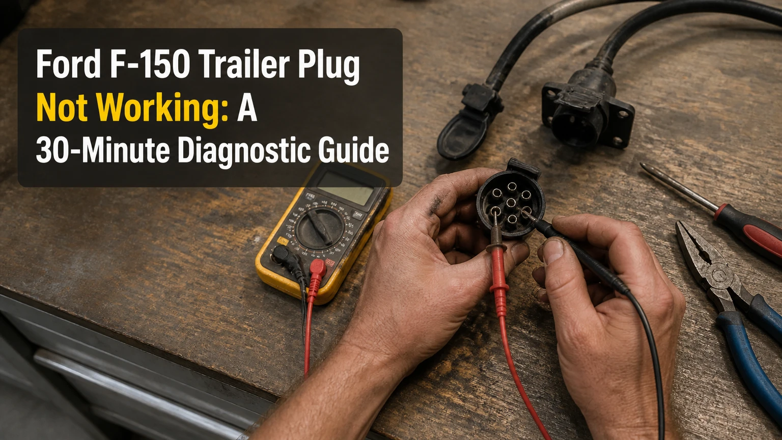
A Ford F-150 trailer plug that is not working usually has a failed ground, corroded socket, blown tow fuse, damaged rear harness, or trailer-side fault. Test the truck’s 4-pin or 7-pin connector with the trailer disconnected first; voltage at the socket points toward the trailer, while missing voltage sends the diagnosis into the F-150 wiring, fuses, or Trailer Tow Module.
Key Facts
A healthy F-150 trailer-light circuit should produce approximately battery voltage, typically 12.2-12.8 volts with the engine off and 13.5-14.8 volts with the engine running.
A dedicated trailer ground wire is more reliable than grounding through the hitch ball, coupler, or trailer frame.
Ford fuse numbers vary substantially by model year, engine, trim, and factory towing equipment; verify every fuse against the owner’s manual or fuse-box diagram.
A 7-pin socket adds electric-brake output, reverse lamps, and auxiliary battery power to the basic lighting circuits.
Power at the truck socket with the trailer disconnected means the truck is probably functional and the trailer or adapter needs testing.
A trailer-light warning can result from high resistance, an open circuit, a short, or an incompatible LED load, not only from a failed control module.
Why Is Your Ford F-150 Trailer Plug Not Working?
The fastest diagnosis is to separate the F-150 from the trailer and test the truck socket function by function. If the running, left-turn, right-turn, and brake terminals show the expected voltage, inspect the trailer plug, ground, lamps, and wiring; if the terminals remain dead, inspect the truck fuse supply, socket, rear harness, and trailer-control electronics.
A trailer connector is a weather-exposed electrical junction located beside the hitch receiver. Road salt, water, pressure washing, crushed wiring, and loose terminal tension affect the socket more often than a failed dashboard control.
Ford’s electrical architecture differs by year. Older F-150s may use more conventional trailer relays and dedicated circuits, while many later trucks use a Trailer Tow Module or related body-control logic to monitor trailer continuity. That monitoring can report “Trailer Disconnected” or a trailer wiring fault when the circuit has resistance outside its expected range.
What the warning message actually means
A “Trailer Disconnected” message does not prove that the trailer physically separated from the truck. The message can appear when a socket terminal is oxidized, a ground is open, a marker-lamp wire is broken, or a trailer has an incompatible lighting load.
Ford’s owner-manual fuse guidance provides a useful safety rule: “Always replace a fuse with one that has the specified amperage rating.” A higher-rated fuse can overheat the harness instead of solving the fault.
How Does the F-150 Trailer Circuit Work?
The F-150 sends lighting commands through the body electrical system and, on equipped models, a Trailer Tow Module that manages or monitors trailer outputs. The connector then distributes separate circuits for ground, tail lamps, stop and turn lamps, electric brakes, reverse lamps, and auxiliary power.
The module does not create power from nothing. A missing fuse, open harness, poor ground, damaged connector, or shorted trailer can prevent a correct output even when the module itself is operating normally.
The circuit also has two different diagnostic properties:
- Lighting output: Usually pulses or remains near battery voltage when the relevant truck control is active.
- Module monitoring: May use low-current sensing or load detection, so a digital meter can show a small ghost voltage even when the circuit cannot power a lamp.
That second condition matters. A meter reading of 5 or 8 volts on an unloaded circuit does not equal a usable 12-volt supply. Confirm suspicious readings with a test lamp or a load-rated trailer tester.
What voltage should the trailer socket show?
A typical F-150 socket should show 12.2-12.8 volts with the engine off and a charged battery, or about 13.5-14.8 volts while the alternator is charging. Voltage should be measured between the active circuit and the socket’s dedicated ground, not merely between the active circuit and the bumper.
| Test condition | Typical reading | Meaning |
|---|---|---|
| Battery, engine off | 12.2-12.8 V DC | Normal charged-system range |
| Engine running | 13.5-14.8 V DC | Typical charging-system range |
| Active circuit to dedicated ground | Within 0.5 V of battery | Strong socket supply |
| Active circuit to bumper only | Variable | Ground reference may be misleading |
| Circuit with no control active | 0-2 V, sometimes ghost voltage | Usually inactive or monitored circuit |
Which Connector Is on an F-150?
A factory-equipped F-150 commonly has a 4-pin flat connector, a 7-pin RV-style blade connector, or both in a shared rear housing. Connector availability depends on towing package, model year, trim, and market, so the socket’s physical presence does not prove that every circuit is wired.
A 4-pin connector carries basic lighting only. A 7-pin connector adds circuits needed by travel trailers and electric-brake-equipped trailers.
| Connector | Circuit count | Main functions | Typical trailer |
|---|---|---|---|
| 4-pin flat | 4 | Ground, tail lamps, left stop/turn, right stop/turn | Utility trailer, small boat trailer |
| 5-pin flat | 5 | 4-pin functions plus auxiliary reverse-lockout circuit | Hydraulic surge-brake trailer |
| 7-pin blade | 7 | Lighting, ground, electric brakes, reverse, auxiliary 12 V | Camper, equipment trailer |
| 7-pin with adapter | 4-7 | Depends on adapter wiring | Mixed tow-vehicle equipment |
What is the standard 7-pin blade pinout?
The common North American 7-way blade arrangement uses dedicated circuits for ground, brakes, tail lamps, battery feed, left stop/turn, right stop/turn, and reverse. The cavity orientation must be identified from the socket face or a diagram because looking at the wire side reverses the apparent layout.
| Function | Common wire color | Typical circuit behavior | Important limitation |
|---|---|---|---|
| Ground | White | Return path for all trailer circuits | Must connect to the truck ground terminal |
| Electric brakes | Blue | Variable controller output, often 0-12 V | Not a constant 12 V feed |
| Tail/running lamps | Brown | Battery voltage with lamps switched on | Supplies marker and rear lamps |
| Auxiliary battery | Black or orange | Battery or charging voltage | May be fuse-controlled or ignition-controlled |
| Left stop/turn | Yellow | Pulsed turn signal, steady brake output | Test with hazards and brake pedal |
| Right stop/turn | Green | Pulsed turn signal, steady brake output | Test independently |
| Reverse lamps | Purple | Battery voltage in Reverse | May support surge-brake lockout |
Wire colors are conventions, not proof. Ford and trailer manufacturers can alter colors, especially after repairs or aftermarket harness installation. Trust the terminal function and a verified diagram.
What Tools and Conditions Are Needed?
A basic diagnosis takes 20-45 minutes and requires a digital multimeter or 4-pin/7-pin circuit tester, a small inspection light, electrical contact cleaner, a nylon brush, and the correct fuse puller. The truck should be parked safely, the trailer disconnected, and the ignition switched on only when the relevant circuit must be energized.
| Tool or material | Quantity | Typical cost | Use |
|---|---|---|---|
| Digital multimeter | 1 | $15-$60 | Voltage and continuity checks |
| 4-way or 7-way tester | 1 | $8-$35 | Fast socket output check |
| Electrical contact cleaner | 1 can | $6-$12 | Removes contamination |
| Nylon terminal brush | 1 | $3-$10 | Cleans corrosion without aggressive metal removal |
| Correct replacement fuse | 1-3 | $1-$8 each | Restores a confirmed blown circuit |
Do not perform an ohms or continuity test on an energized circuit. Disconnect the trailer and switch the circuit off before using resistance mode.
How Do You Diagnose a Dead F-150 Trailer Socket?
Diagnose from the socket outward, then move toward the fuse box and module. The sequence below isolates the fault without replacing expensive components prematurely.
Step 1: Confirm the symptom with the trailer disconnected
Switch off the truck, unplug the trailer, and inspect the socket cover, terminals, and mounting bracket. Remove any adapter because an internally broken adapter can imitate a failed F-150 connector.
Reconnect the truck battery only if it was previously disconnected. Turn on the ignition, activate the parking lamps, and use the hazards for the left and right stop/turn circuits.
Success checkpoint: The socket is clean, mechanically secure, and accessible for testing.
Common mistake: Testing through a 7-to-4-pin adapter first. Test the native truck socket before adding another connection.
Step 2: Test the ground before testing every output
Set the multimeter to DC volts. Connect the black probe to the socket ground terminal and the red probe to battery positive, or use a known battery negative reference for comparison.
A ground-side voltage-drop test is more informative under load. Connect a test lamp between battery positive and the socket ground; a bright lamp indicates a usable ground path, while a dim or dead lamp indicates excessive resistance or an open ground.
Success checkpoint: The socket ground produces nearly the same result as the battery negative terminal.
Common mistake: Using the hitch ball as the only ground. Paint, rust, grease, and a coated coupler can interrupt that path.
Step 3: Check each lighting function at the socket
Use the socket diagram for your connector and test one circuit at a time. With the running lights on, test the tail-lamp terminal; with hazards on, test both stop/turn terminals; press the brake pedal to confirm steady brake voltage.
| Function | Control setting | Expected observation |
|---|---|---|
| Running lamps | Headlamp switch on | Steady battery-level voltage |
| Left turn | Left indicator or hazards | Pulsing battery-level voltage |
| Right turn | Right indicator or hazards | Pulsing battery-level voltage |
| Brake lamps | Brake pedal pressed | Steady voltage on both stop/turn terminals |
| Reverse lamps | Transmission in Reverse, brake applied | Voltage on reverse terminal |
| Electric brakes | Manual controller lever | Variable controller output |
| Auxiliary power | Ignition or engine state varies | Battery-level voltage only if equipped |
Success checkpoint: Every required circuit produces a stable or pulsing output appropriate to its function.
Common mistake: Calling a circuit dead because the meter shows a brief reading. Repeat the test with a trailer tester or incandescent test lamp.
Step 4: Inspect year-specific tow fuses and relays
Locate the engine-compartment power distribution box and, where fitted, the passenger-compartment fuse panel. Use the owner’s manual for the exact year and equipment configuration because fuse numbers such as 8, 10, 19, 21, 43, 60, 73, or 81 are not universal F-150 assignments.
A visual inspection can miss a hairline fuse break. Test both fuse test points with the circuit energized, or remove the fuse and verify continuity with power disconnected.
| Fault symptom | Fuse or supply area to verify | Why the number varies |
|---|---|---|
| Running lamps absent | Trailer park-lamp fuse or relay | Model year and body-control layout |
| Both stop/turn outputs absent | Trailer stop/turn supply | Tow-package and engine differences |
| Electric brakes absent | Brake-controller fuse and controller feed | Integrated controller equipment |
| Auxiliary 12 V absent | Trailer battery-feed fuse or relay | Factory charging strategy |
| All trailer functions absent | Module power, ground, main tow fuse | Connector or harness failure also possible |
Replace a failed fuse only once, with the same amperage and type. If the replacement opens immediately, a short exists in the truck harness, socket, adapter, or trailer.
Success checkpoint: The fuse has correct amperage, power reaches both test points, and the replacement remains intact.
Common mistake: Installing a 30-amp fuse where a 20-amp fuse belongs because the circuit keeps blowing.
Step 5: Inspect the rear socket and harness junction
Follow the tow harness behind the bumper, near the spare tire, and along the frame rail. Disconnect the rear socket connector only after switching the ignition off, then inspect for green oxidation, pushed-back terminals, broken locks, water tracks, and wires rubbed through against the frame.
A socket can look clean from the front while its rear connector is heavily corroded. Terminal tension also matters: a female terminal that no longer grips its blade can pass a light test intermittently and fail when the trailer vibrates.
Success checkpoint: The rear junction is dry, locked, free of green corrosion, and protected from sharp edges.
Common mistake: Spraying cleaner into a connected module and immediately applying power. Allow solvent to evaporate fully.
Step 6: Check under-dash towing connections
Inspect the factory brake-controller connector and related harness near the driver’s lower dash, especially after aftermarket controller installation or trim-panel work. Confirm that locking tabs are engaged and that no terminal has moved backward inside the connector.
This step matters most when the trailer brake output, controller display, or trailer-status message fails while the lighting circuits still work.
Success checkpoint: The controller connector is fully seated, terminals are aligned, and the harness has no pulled wires.
Common mistake: Replacing the integrated brake controller before testing the rear socket and brake-output circuit.
What If the Truck Socket Has Power but the Trailer Lights Do Not?
Power at the disconnected F-150 socket shifts the diagnosis to the trailer, adapter, or plug. Start with the trailer’s ground terminal and white ground wire, then inspect the plug strain relief, junction box, lamp sockets, bulbs, LED modules, and frame-mounted wiring.
Connect the trailer and repeat the voltage test at the trailer plug. If voltage exists at the truck but disappears at the trailer plug, the adapter or truck-side socket has poor terminal contact. If voltage reaches the trailer plug but not a lamp, trace the trailer harness.
The trailer ground should connect directly from the plug to the trailer wiring junction and preferably to each lamp ground. Aluminum frames, painted couplers, powder coating, and rusty mounting screws make frame-only grounding unreliable.
Why do trailer lights flicker or work only when connected?
Intermittent trailer lights usually indicate a high-resistance ground, loose socket terminal, broken conductor near the tongue, or a damaged plug strain relief. A circuit may pass a meter test with no load and fail when lamps draw current.
Perform a voltage-drop test with the trailer lamps on. Measure between the truck socket ground and the trailer lamp ground; more than about 0.5 volts under load indicates excessive resistance in the return path.
Why Are the Trailer Brakes Not Working?
Trailer brakes use a separate 7-pin circuit and cannot operate through a 4-pin connector. If the F-150 lighting works but the brakes do not, test the blue brake-output terminal while applying the manual slide on the integrated trailer brake controller, then inspect the trailer brake wiring, magnets, and ground.
Brake output is normally variable rather than a fixed battery feed. The controller increases voltage according to its gain setting and braking demand, so a zero reading with the manual lever applied points toward the controller supply, fuse, connector, or output circuit.
Do not confuse the auxiliary 12-volt terminal with brake output. The auxiliary terminal may charge a trailer battery, while the blue terminal carries controlled brake voltage.
When should you stop towing?
Do not tow when the trailer has no stop lamps, no turn signals, no reliable ground, overheated wiring, exposed conductors, or brakes that fail on a trailer requiring them. A functioning truck-side socket does not make an electrically unsafe trailer safe for the road.
How Much Does F-150 Trailer-Plug Repair Cost?
Typical repair cost ranges from $5 for a fuse to more than $1,000 for extensive harness replacement. A socket replacement is often the best-value repair when corrosion or loose terminals are visible and the rear harness tests correctly.
| Repair | Parts range | Shop labor range | Typical time |
|---|---|---|---|
| Fuse or relay replacement | $1-$20 | $50-$100 minimum | 10-20 minutes |
| OEM-style socket replacement | $25-$75 | $50-$150 | 30-60 minutes |
| Rear tow sub-harness | $80-$180 | $120-$300 | 1-2 hours |
| Local wire or terminal repair | $10-$40 | $150-$450 | 1-3 hours |
| Trailer-control diagnosis | $0-$150 scan time | $100-$250 | 1-2 hours |
| Complete harness replacement | $300-$800 | $700-$1,500 | 5-10 hours |
These are typical North American ranges, not Ford-published prices. Dealer labor rates, corrosion severity, access, and factory versus aftermarket wiring change the final estimate.
Which Repair Approach Fits Your Situation?
The correct repair depends on the failed function, not on the warning message alone. Basic lighting faults usually need cleaning, a ground repair, a socket, or a fuse; module faults deserve scan-tool confirmation after the physical circuit passes inspection.
| Situation | Most likely cause | First action | Avoid |
|---|---|---|---|
| All trailer functions dead | Ground, main fuse, socket connector | Test ground and battery feed | Replacing the module first |
| Running lamps only dead | Park-lamp fuse, brown wire, socket terminal | Test tail circuit at socket | Blaming the trailer bulbs |
| One turn signal dead | Terminal, rear harness, trailer wire | Compare left and right outputs | Swapping unrelated fuses |
| Lights work, brakes fail | Blue circuit, controller, trailer magnets | Test manual controller output | Using auxiliary power as brake power |
| Works in dry weather only | Corrosion or water intrusion | Inspect rear socket and junction | Filling socket with heavy grease |
| Warning appears with LED trailer | Load detection or wiring resistance | Test with approved load or tester | Assuming the module is defective |
Dielectric silicone grease belongs on clean, dry connector surfaces as a moisture barrier. It does not restore a broken wire, improve a loose terminal, or replace electrical contact.
Can an Adapter Cause the Failure?
A 7-to-4-pin adapter can cause complete or partial trailer-light failure when its blades are loose, its internal crimps are damaged, or its ground terminal is corroded. Remove the adapter and test the F-150’s native connector before replacing truck components.
Adapters also cannot create circuits that the source connector does not provide. A 4-pin-to-7-pin adapter can carry basic lighting, but it cannot supply genuine electric-brake control, reverse lamps, or a correctly protected auxiliary battery feed unless those circuits are separately wired.
What Are the Most Common Diagnostic Mistakes?
The most expensive mistakes come from treating a warning message as a component diagnosis. Test the circuit first, then identify the failed part.
- Testing with the trailer still connected: A trailer short can pull down the truck output and hide a healthy socket. Disconnect first.
- Using chassis metal as the meter ground: A painted bumper can produce a false pass or false failure. Use the socket ground terminal and battery negative for comparison.
- Replacing fuses by number from another year: F-150 fuse assignments change with generation and options. Verify the diagram.
- Testing only with a digital meter: A high-impedance meter can display ghost voltage. Confirm doubtful circuits under load.
- Replacing the trailer module immediately: Corroded sockets, broken frame-rail wires, and loose grounds are more accessible causes.
- Applying grease before cleaning: Grease over oxidation preserves a poor connection. Clean, dry, tighten, then seal.
An experienced wiring technician checks terminal tension, not only continuity. A wire can show continuity through a damaged crimp while its terminal cannot carry lamp current.
What Should You Check After the Repair?
After repair, test every required function with the trailer connected and the engine running. Confirm running lamps, both turn signals, brake lamps, reverse lamps if used, electric-brake response, and auxiliary charging voltage.
Secure the harness at least several inches away from exhaust components, suspension travel, tire edges, and sharp frame holes. Replace damaged convoluted loom and use clips or abrasion protection rather than pulling the harness tight.
Clear any stored trailer-related diagnostic code with a compatible scan tool only after the physical fault is corrected. A code may return if the module still detects an open or shorted circuit.
Frequently Asked Questions
Why does my F-150 say trailer disconnected when the trailer is connected?
An F-150 can display “Trailer Disconnected” when the trailer ground is open, the socket has corrosion, or the monitored lighting load is outside the expected range. Inspect the white ground wire, clean the 7-pin terminals, and test the running-lamp circuit under load before replacing the Trailer Tow Module.
Does a 7-pin trailer plug always have 12-volt power?
A factory 7-pin F-150 connector may have an auxiliary 12-volt circuit, but the circuit can be fuse-controlled, relay-controlled, ignition-dependent, or absent on an improperly equipped or modified truck. Measure the auxiliary terminal against the dedicated ground with the truck configured according to its owner’s manual.
Why do my F-150 trailer lights work without the trailer but fail when connected?
The trailer may contain a shorted lamp, crushed wire, failed LED module, or poor ground that loads the circuit down. Test the socket unloaded, then test at the trailer plug while connected; a large voltage drop identifies a connection or trailer-load problem.
Can a blown fuse make only one trailer light stop working?
A blown fuse can disable one function, such as running lamps or stop/turn outputs, but one side alone more often indicates a loose terminal, damaged wire, or trailer-side lamp circuit. Compare the left and right socket outputs with the hazards operating.
How do I clean a corroded Ford trailer connector?
Disconnect the harness, remove loose oxidation with electrical contact cleaner and a nylon brush, allow the connector to dry, and check terminal tension before reconnecting it. Replace terminals or the complete socket when corrosion has caused pitting, looseness, heat damage, or recurring failure.
Is it safe to tow with a trailer wiring fault warning?
Towing is unsafe when the warning accompanies missing lights, unreliable brakes, exposed wiring, or an unknown ground condition. Perform a complete socket and trailer test first, because a warning can identify a genuine loss of required lighting even when some functions still operate.
The Bottom Line
When a Ford F-150 trailer plug is not working, disconnect the trailer, test the dedicated ground, measure each socket circuit, and then inspect the year-specific tow fuses, rear harness, socket terminals, and brake-controller connections. Power at the socket moves the fault to the trailer or adapter; no power keeps the diagnosis within the F-150. Repair the verified circuit before towing, and never substitute a higher-rated fuse or hitch-ball ground for the factory electrical path.