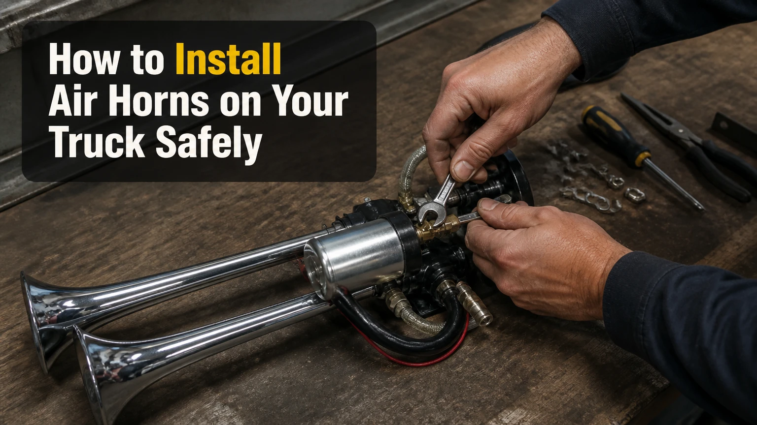
To install air horns on your truck, mount the trumpets and air tank securely, connect a 12V compressor through a fused relay, plumb DOT-rated air line through a solenoid valve, and connect the horn trigger without overloading the factory circuit. Plan 3-6 hours, depending mainly on available mounting space and access to the battery and frame.
Key Facts
A complete truck air horn system normally includes trumpets, a compressor, an air tank, a solenoid valve, a pressure switch, a pressure-relief valve, fittings, and wiring.
A 1.5-3 gallon tank suits most daily-driven pickups, while locomotive-style horns often require 5 gallons or more.
The compressor must receive power through a correctly sized fuse and relay, not through a dashboard switch or factory horn wire.
Mount trumpets downward or slightly forward so rain, mud, salt, and gravel cannot collect inside the horn diaphragms.
Drain the tank regularly because compressed air creates condensation that can cause corrosion and valve problems.
A horn system can exceed 130 dB, so test it away from people, animals, buildings, and traffic.
What You Need Before Starting
A truck air horn installation requires mechanical hardware, pneumatic hardware, and a dedicated electrical circuit. Confirm the kit’s pressure rating, current draw, fitting sizes, and wiring diagram before drilling or cutting, because similar-looking kits often use different solenoids, pressure switches, and air-line diameters.
Parts and tools checklist
| Item | Typical specification | Quantity or size | Purpose |
|---|---|---|---|
| Air horn trumpets | 12V pneumatic, 110-155 dB claimed range | 1-4 trumpets | Produces the sound |
| Air tank | 1.5-5 gallons, 120-200 PSI rated | 1 | Stores compressed air |
| Compressor | 12V, 120-200 PSI, 15-40 amp draw | 1-2 | Fills the tank |
| Solenoid valve | 12V, tank-pressure rated | 1 | Releases air to the horns |
| Relay and fuse | 30-40 amp relay, manufacturer-sized fuse | 1 each | Switches compressor current safely |
| Air line | DOT-rated nylon or approved equivalent | 5/16 or 1/2 inch typical | Carries compressed air |
| Electrical cable | 10-12 AWG for many compressors | 3-8 feet typical | Reduces voltage drop |
| Mounting hardware | Grade 5 or metric equivalent, lock nuts | 6-12 fasteners | Secures components |
| Tools | Drill, bits, crimper, multimeter, wire stripper | 1 set | Installation and testing |
| Sealant | Pneumatic thread sealant | 1 tube | Seals tapered threads |
The fuse value must follow the compressor manufacturer’s instructions and measured operating load. A 30-amp compressor does not automatically require a 30-amp fuse, because the fuse must tolerate normal startup current while still protecting the wire. Never increase fuse size to stop repeated blowing without finding the underlying overload or short.
Check local rules before installation
Air horns may be restricted by vehicle equipment laws, inspection rules, or local noise ordinances. The United States does not have one universal aftermarket air-horn rule for every truck, and requirements vary by state, municipality, vehicle class, and whether the horn is used on public roads.
Retain the factory horn when practical. A loud train-style horn is poorly suited to routine low-speed signaling, parking-lot use, or situations where a conventional horn is legally required. Check your state inspection authority and local traffic code before connecting an exceptionally loud system to the steering-wheel horn button.
How an Air Horn System Works
A pneumatic air horn converts stored compressed air into sound through a valve and resonating trumpet. Pressing a button energizes the 12V solenoid, the solenoid opens the air path, and tank pressure moves through the horn diaphragm, which vibrates and creates the audible tone.
The compressor does not normally create the full horn blast directly. The compressor fills the tank until the pressure switch reaches its cut-out setting, such as 120-150 PSI on a typical kit. When the pressure falls below the switch’s cut-in setting, often 90-120 PSI, the compressor runs again.
The tank provides immediate airflow, which eliminates the delay common with compact direct-drive horns. Trumpet length and internal design shape the tone, while tank volume and compressor recovery determine how long repeated blasts remain strong. The solenoid controls air release, not compressor operation.
One important correction is that not every horn uses the same diaphragm design. Some train-style horns use a vibrating diaphragm, while kit construction and valve arrangements differ by manufacturer. Follow the supplied diagram rather than assuming every trumpet has identical ports or pressure requirements.
Which System Fits Your Truck?
A compact direct-drive horn fits small spaces, but a tank-based system gives faster response and stronger repeated blasts. For most daily-driven full-size pickups, a 1.5-3 gallon tank and a compressor rated around 120-150 PSI provide a practical balance between sound, installation space, recovery time, and cost.
| System type | Tank and pressure | Typical current | Typical cost | Best application |
|---|---|---|---|---|
| Compact direct-drive | No tank, 15-20 PSI at horn | 10-20 amps | $30-$80 | Small truck, occasional use |
| Basic multi-trumpet | 0.8-1.5 gallons, 120-150 PSI | 15-30 amps | $100-$250 | Budget daily driver |
| Standard train-horn kit | 1.5-3 gallons, 130-150 PSI | 20-40 amps | $150-$400 | Full-size pickup |
| Heavy-duty onboard air | 2.5-5 gallons, 150-200 PSI | 30-60 amps | $300-$800 | Off-road or tire inflation |
| Locomotive-style system | 5-10 gallons, 150-200 PSI | 40-80 amps total | $600-$1,500 or more | Show truck or specialty build |
Manufacturer decibel ratings are usually measured under specified conditions and are not directly comparable across brands. A claimed 150 dB does not mean every installation will produce 150 dB at the same distance, because pressure, trumpet orientation, airflow, microphone position, and surrounding surfaces change the result.
Train horns are also poor substitutes for an air-tool system unless the compressor has an appropriate duty cycle and airflow rating. A compressor can reach 150 PSI yet deliver too little cubic feet per minute to inflate a large tire efficiently.
Step 1: Plan the Layout and Disconnect Power
Choose mounting locations before removing trim or drilling the frame. Disconnect the negative battery cable, inspect both sides of every drilling surface, and keep the tank, compressor, air line, and wiring away from exhaust heat, suspension travel, driveshafts, steering components, fuel lines, brake lines, and sharp frame edges.
Use cardboard templates for the tank and trumpet brackets. Check that the truck can still receive a spare tire, bed liner, mud flap, skid plate, or future suspension component. Leave enough room to remove the compressor filter, access the pressure switch, read the gauge, and open the tank drain.
A practical layout usually places the horns behind the front bumper, between frame rails, under the bed, or inside a protected bed-side compartment. The compressor should be near the tank, while the horns can be farther away if the air line remains protected and properly supported.
You will know the layout works when: every component has a service path, the trumpets have clear sound openings, and no moving or hot part can contact the system.
Common mistake: choosing a hidden location that makes the drain valve or compressor filter impossible to reach.
Step 2: Mount the Horns, Tank, and Compressor
Mount each component to structural metal with properly sized fasteners, locking hardware, and corrosion protection. Do not rely on thin plastic bumper covers, bed liners, zip ties, or a single self-tapping screw for a heavy tank or locomotive trumpet.
Point the trumpets downward or slightly forward. Downward orientation reduces water and road-debris entry, but leave enough clearance for sound dispersion and avoid directing the outlet toward the cabin, pedestrians, or a nearby microphone. Add a grille or splash shield only if it does not obstruct airflow.
Install the tank horizontally or according to the kit instructions, with the drain at the lowest practical point. A tank mounted upside down can trap water, and a tank mounted directly against the frame can transfer vibration and develop bracket fatigue.
Install the compressor on rubber isolators. Keep the intake filter away from wheel spray and dust, and position the compressor so its motor and head can shed heat. Many compact compressors require rest periods, while a 100% duty-cycle unit can run continuously only within its published temperature and pressure limits.
You will know the mounting is sound when: the brackets do not flex by hand, fasteners remain clear of wiring, and suspension compression leaves safe clearance.
Common mistake: mounting the horns upward. The trumpet becomes a water funnel, and moisture can corrode the diaphragm or freeze in cold weather.
Step 3: Plumb the Compressor, Tank, and Solenoid
Connect the compressor outlet to the tank with the supplied high-temperature leader hose or another line approved for compressor discharge temperature and pressure. Do not replace a hot-side leader hose with ordinary nylon air line unless the manufacturer specifically permits it.
Use DOT-rated air line for the tank-to-solenoid circuit when the kit calls for it. Cut tubing squarely with a dedicated cutter, insert push-to-connect tubing fully, and maintain the manufacturer’s minimum bend radius. Keep the line away from exhaust pipes, suspension movement, and abrasion points, securing it approximately every 12-18 inches.
Apply pneumatic thread sealant to tapered pipe threads, leaving the first thread free of sealant so fragments cannot enter a valve. PTFE tape can work on suitable stationary tapered threads, but excess tape or poorly wrapped tape can contaminate the solenoid. Do not seal compression ferrules, O-rings, or push-to-connect tubing with tape.
A typical flow path is:
Compressor → check valve or leader hose → tank → solenoid valve → trumpets
The check valve prevents stored tank pressure from forcing air backward through the compressor. The solenoid should be rated for the tank’s maximum pressure and installed in the direction marked by its flow arrow.
You will know the plumbing is correct when: tubing follows a smooth route, every port matches the kit diagram, and no line touches a heat source or moving component.
Common mistake: using a low-pressure accessory hose on the tank outlet. A hose rated only for 20-30 PSI is unsuitable for a 120-200 PSI tank.
Step 4: Install the Pressure Switch, Gauge, Relief Valve, and Drain
Install a pressure switch in a tank port or manifold position specified by the kit manufacturer. A pressure switch commonly turns the compressor on around 90-120 PSI and off around 120-150 PSI, but the correct settings depend on the compressor, tank, solenoid, and horn design.
The tank also needs a pressure gauge, a safety relief valve, and a drain valve. The relief valve must be rated at or below the tank’s permitted maximum pressure, and the drain should occupy the lowest tank port. Never plug a supplied relief-valve port or substitute a decorative fitting.
Use the gauge to distinguish a compressor problem from a horn problem. A full tank with no blast points toward the solenoid, trigger circuit, blocked line, or horn diaphragm. A tank that never reaches cut-out pressure points toward compressor power, a leak, a check valve, or a damaged compressor.
After assembly, charge the tank and brush diluted dish soap over every threaded connection, valve body, and push fitting. Bubbles identify leaks. Depressurize the system before tightening a fitting, and never tighten a pressurized pneumatic connection.
You will know the pressure controls work when: the compressor stops at its intended cut-out pressure, restarts after pressure falls, and the relief valve remains unused during normal operation.
Common mistake: setting the pressure switch above the tank or compressor rating. The lowest-rated component controls the safe maximum pressure.
Step 5: Wire the Compressor and Horn Trigger
Power the compressor from the battery through a properly sized fuse and relay. Use short, adequately thick cable for the high-current path, protect the cable in loom, and place the fuse close to the battery positive terminal so an accidental ground cannot turn the entire cable into an unfused heating element.
A common relay arrangement uses standard automotive terminal numbers:
| Relay terminal | Connection | Typical wire approach |
|---|---|---|
| 30 | Fused battery positive | 10-12 AWG for many 20-40 amp compressors |
| 87 | Compressor positive | Same gauge as terminal 30 |
| 85 | Ground | 12-14 AWG, clean chassis point |
| 86 | Switched control power | 16-18 AWG control circuit |
| Compressor negative | Chassis or battery negative | Same current capacity as positive lead |
| Solenoid positive | Horn button or solenoid relay output | Kit-specified control wire |
| Solenoid negative | Chassis or battery negative | Protected ground connection |
The pressure switch normally controls the compressor relay coil, not the compressor motor directly. A switched ignition feed can pass through an enable switch and the pressure switch before reaching terminal 86, while terminal 85 connects to ground. This arrangement lets the pressure switch cycle the compressor automatically without leaving the motor on a dashboard switch.
The horn trigger circuit is separate. A factory horn wire may switch positive or ground, and modern trucks can use body-control modules, so test the circuit with a wiring diagram and multimeter before tapping it. If the factory signal cannot safely drive the solenoid, use an additional relay or a dedicated momentary button.
Retain the original horn through a changeover relay or separate switch when possible. This gives the driver a low-volume signaling option and reduces the chance of misusing a train-style horn in traffic.
You will know the wiring is correct when: the compressor starts only below the cut-in pressure, the fuse remains cool, the solenoid opens only when commanded, and the factory horn circuit shows no warning lights or diagnostic faults.
Common mistake: connecting a 20-40 amp compressor directly to a toggle switch. The switch contacts can overheat, weld closed, or fail without opening the circuit protection.
Step 6: Charge, Leak-Test, and Test the Horn
Reconnect the battery, turn on the compressor enable circuit, and observe the first pressure cycle. Keep hands, clothing, and tools away from the compressor belt or fan, and stop immediately if wiring heats, the motor stalls, or a fitting sprays air.
Let the compressor reach cut-out pressure, then switch it off and record the gauge reading. Leave the system undisturbed for 30 minutes, or overnight for a more demanding test. A small gauge change can result from temperature variation, but a clear pressure loss indicates a leak that must be found.
Test the solenoid briefly in an open area. Stand away from the trumpet outlets and warn anyone nearby, because a 130-155 dB horn can cause hearing injury and startle people at close range. Do not test inside a garage or beside a house wall.
Spray soap solution over all joints after the system reaches pressure. Repair bubbling fittings, then repeat the test. Finally, confirm that the compressor cuts in after several short blasts and that no air line has moved into a tire, driveshaft, or exhaust path.
Cost, Time, and Difficulty
A basic truck air horn installation typically costs $150-$400 for the kit plus $30-$150 for wire, brackets, fittings, loom, and protective hardware. Heavy-duty systems with large tanks, dual compressors, and locomotive trumpets can exceed $1,000 before labor.
| Installation scope | Parts cost | DIY time | Main difficulty |
|---|---|---|---|
| Compact direct-drive horn | $30-$100 | 1-2 hours | Finding a protected mount |
| Standard 1.5-3 gallon kit | $180-$500 | 3-6 hours | Tank access and wiring |
| Off-road onboard-air system | $350-$900 | 5-8 hours | Heat, debris, and air-line routing |
| Locomotive-style build | $700-$1,800 | 6-12 hours | Heavy brackets and high current |
| Professional installation | $250-$900 labor | 2-6 hours | Vehicle-specific access |
A truck with an accessible battery, open frame rails, and preexisting auxiliary switches usually falls near the lower time range. Rusted fasteners, a sealed engine bay, a body-control-module horn circuit, or a hidden tank location can add several hours.
Common Mistakes and How to Fix Them
| Symptom or mistake | Likely cause | Corrective action |
|---|---|---|
| Compressor never starts | Empty control power, bad ground, blown fuse, full tank | Test voltage at relay terminals, clean ground, bleed tank, replace fuse only after checking load |
| Compressor runs constantly | Air leak, loose fitting, failed check valve, undersized compressor | Soap-test fittings, inspect valve, verify compressor duty cycle |
| Solenoid clicks but horn is silent | No tank pressure, blocked line, wrong flow direction, stuck diaphragm | Confirm gauge pressure, inspect arrow and tubing, clean or replace valve |
| Horn sounds weak | Low voltage, low tank pressure, small air line, restrictive fitting | Measure compressor voltage under load, restore pressure, follow kit line size |
| Pressure drops overnight | Thread leak, cracked tube, leaking solenoid | Isolate sections, use soap solution, replace damaged tubing or seal |
| Fuse blows repeatedly | Motor overload, shorted cable, wrong fuse, poor compressor | Measure current, inspect loom, verify manufacturer fuse and ground |
| Horn fills with water | Trumpets aimed upward or unprotected | Reorient outlets downward, dry the horn, add a suitable splash shield |
A clean-looking installation can still fail electrically. Paint, powder coating, and frame rust often create enough resistance to prevent a compressor relay from closing reliably, so grind only the ground contact area to bare metal and protect the finished connection against corrosion.
Another practitioner rule is to diagnose pressure before diagnosing sound. If the gauge reads zero, replacing a solenoid or trumpet wastes time. If the tank holds pressure but the horn does not sound, focus on the solenoid trigger, valve direction, and horn diaphragm.
Variations for Different Truck Uses
Daily-driver pickup
Use a standard 1.5-3 gallon kit, retain the factory horn, and mount the compressor behind splash protection. A moderate tank reduces compressor cycling during normal use and fits more easily than a 5-10 gallon reservoir.
Off-road and overlanding truck
Use a protected compressor with a suitable duty cycle, a 2.5-5 gallon tank, a moisture-resistant intake, and abrasion-resistant air line. If the same system will inflate 35-inch tires, select the compressor by airflow at working pressure, not by its maximum PSI number.
Air horns should not share an unprotected air line with an air locker or tire-inflation circuit without proper check valves, manifolds, and pressure regulation. A failed horn solenoid should not be able to drain equipment that controls vehicle traction.
Show truck or locomotive-style installation
Use reinforced brackets, dual compressors where the manufacturer requires them, and a 5-10 gallon tank only when the frame and mounting structure can carry the weight. Large trumpets need clear outlets, but they also create more exposure to theft, weather, and legal noise complaints.
Locomotive horns are not a sensible choice for enclosed neighborhoods, frequent urban signaling, or trucks with limited electrical capacity. Their sound is impressive, but their airflow demand, weight, and installation footprint are substantial.
Maintenance After Installation
Drain the tank at least monthly in dry conditions and more often in humid or salty climates. Open the drain with the tank depressurized or at low pressure according to the tank instructions, and inspect the expelled water for rust particles or oil.
Inspect mounting bolts, relay terminals, fuse holders, hose abrasion, and trumpet openings at each oil change. Clean a compressor intake filter when dirty, and replace damaged push-to-connect tubing rather than repeatedly trimming the same short section.
Before winter, check for moisture accumulation and protect exposed fittings from salt. Water in the solenoid can freeze and prevent the valve from opening even when the electrical trigger works.
FAQ
Can I connect air horns to the factory horn button?
Yes, but the factory horn circuit must be identified first. Some trucks switch power, some switch ground, and newer trucks may control the horn through a body module. Use the factory signal to control a relay or compatible solenoid circuit, and retain the original horn when the kit and vehicle wiring allow it.
Do air horns need an air tank?
A compact direct-drive horn can operate without a storage tank, but tank-based systems provide faster initial response and stronger repeated blasts. A 1.5-3 gallon tank is typical for a daily-driven pickup, while large locomotive horns commonly need 5 gallons or more.
How loud should a truck air horn be?
Many aftermarket kits claim approximately 110-155 dB, depending on trumpet design, pressure, and measurement conditions. Decibel claims are not directly comparable between brands. Treat any system above ordinary automotive-horn volume as a hearing and traffic-safety hazard during testing.
Can I mount the air horns under the hood?
You can mount compact trumpets under the hood if they have adequate clearance and protection, but engine-bay heat and water exposure can shorten component life. The horn outlets must remain unobstructed, and the compressor should have cool, clean intake air rather than hot air beside the exhaust manifold.
Why does my air horn sound weak after installation?
A weak blast usually results from low tank pressure, voltage drop, a restricted air line, an incorrectly sized solenoid, or a damaged diaphragm. Check the gauge first, then measure compressor voltage while running and verify that the air line and solenoid match the kit specifications.
Can one compressor run air horns and inflate tires?
Yes, if the compressor has enough airflow, duty-cycle capacity, and tank volume for both tasks. A maximum-pressure rating alone does not prove tire-inflation performance. Install proper check valves and a regulated outlet so a horn fault cannot compromise an air locker or another pneumatic accessory.
The Bottom Line
To install air horns on your truck successfully, treat the project as a small pneumatic system rather than a simple horn replacement. Secure the tank and trumpets, use heat-rated and DOT-approved air lines, install a relief valve and drain, protect the compressor circuit with the correct fuse and relay, and test every connection under pressure. The exact keyword, how to install air horns on your truck, ultimately leads to one practical rule: build for safe service access, not maximum noise alone.