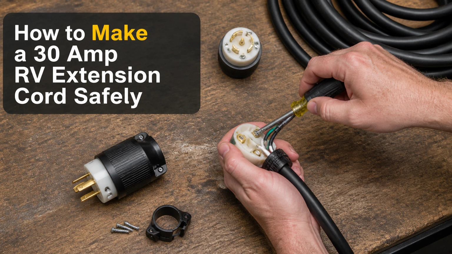
To make a 30-amp RV extension cord, assemble outdoor-rated 10/3 portable cable between a NEMA TT-30P male plug and a NEMA TT-30R female receptacle. Connect black to brass, white to silver, and green to ground, then verify continuity, isolation, polarity, and strain relief before connecting the cord to a live pedestal.
Key Facts at a Glance
- A 30-amp RV extension cord uses a three-conductor, 125-volt NEMA TT-30 configuration.
- A listed 10/3 outdoor portable cord is the normal starting point for a 30-amp extension cord.
- Black connects to hot, white connects to neutral, and green connects to equipment grounding.
- The nominal maximum is 3,600 watts at 120 volts, but continuous loads require lower operating headroom.
- A 100-foot limit is not universal; voltage drop depends on total length, conductor resistance, and actual load.
- A multimeter test cannot replace a visual inspection, correct assembly, or a properly rated connector.
Before You Start
A typical first-time assembly takes 45-90 minutes and requires moderate electrical skill. The main safety factor is not cutting the cable; it is making secure, correctly identified terminations inside connectors rated for the cable diameter and outdoor use.
Disconnect every power source before assembly. Never assemble or test a cord while the plug is connected to a campground pedestal, generator, inverter, or household receptacle.
Materials and Tools
| Item | Typical specification | Quantity or range | Selection requirement |
|---|---|---|---|
| Portable cable | 10/3, three conductors, 125-volt or higher rating | Required length plus 12 inches | Outdoor and wet-location rating, such as STW, SEOOW, or SOOW |
| Male plug | NEMA TT-30P, 30 amperes, 125 volts | 1 | Cord-grip and strain relief must fit the cable |
| Female receptacle | NEMA TT-30R, 30 amperes, 125 volts | 1 | Listed for flexible cord and outdoor service |
| Wire stripper | Capacity including 10 AWG | 1 | Must avoid nicking copper strands |
| Multimeter | AC voltage, resistance, continuity | 1 | Leads rated for mains work |
| Screwdriver | Tip specified by connector manufacturer | 1 | Insulated handle preferred |
| Utility knife | Sharp blade | 1 | Used only on the outer jacket |
| Torque driver | Manufacturer-specified range | Optional | Preferred for repeatable terminal tightening |
Use connectors from a recognized testing laboratory or a reputable electrical manufacturer. Read the plug and receptacle instructions before stripping the jacket because terminal depth, strip length, screw type, and torque differ among products.
How to Make a 30 Amp RV Extension Cord
The process has six practical stages: select compatible parts, prepare both cable ends, terminate the male plug, terminate the female receptacle, inspect the assembly, and test it while disconnected from power. Do not substitute a household 5-15 connector, a 30-amp 250-volt generator connector, or an unlisted cable assembly.
Which Connectors and Cable Should You Buy?
Buy one NEMA TT-30P plug, one NEMA TT-30R receptacle, and enough 10/3 outdoor portable cord for the required distance. NEMA TT-30 has one hot contact, one neutral contact, and one grounding contact, and it is a 125-volt RV connection.
The cable designation matters. STW is usually less expensive and more rigid, while SEOOW and SOOW rubber or elastomer jackets remain easier to handle in cold conditions. The letter W indicates suitability for outdoor or wet locations in the applicable cord designation, but the complete manufacturer marking still controls.
Do not use NM-B building cable, speaker wire, welding cable without the correct listing, or an ordinary indoor extension cord. Flexible portable cord needs mechanical protection, a suitable jacket, and connectors designed for its outside diameter.
| Cable type | Jacket behavior | Typical temperature range | Practical use |
|---|---|---|---|
| 10/3 STW | Vinyl, relatively stiff | About -20 to 60°C, manufacturer-specific | Fair-weather camping and occasional use |
| 10/3 SEOOW | Flexible elastomer | Often about -50 to 105°C, manufacturer-specific | Repeated outdoor use and cooler weather |
| 10/3 SOOW | Flexible thermoset rubber | Often about -40 to 90°C, manufacturer-specific | Heavy-duty, frequent handling |
| 10/3 indoor cord | Indoor jacket | Rating varies, often not wet-location listed | Not suitable for exposed campground use |
Connector markings and cable ratings must agree. A 30-amp plug attached to cable with an unsuitable jacket does not create a compliant outdoor cord.
Step 1: Measure and Cut the Cable
Measure the finished length you actually need, then cut the cable squarely with a cutter rated for 10 AWG conductors. Add approximately 6 inches at each end if the connector instructions allow it, because excess cable makes termination easier and can be trimmed later.
A 50-foot finished cord normally needs about 51 feet of bulk cable, but connector geometry varies. Mark the intended plug end and receptacle end before removing any jacket.
You will know it worked when: the cable reaches between the pedestal and RV inlet without tension, sharp bends, or a connector suspended by the cord.
Common mistake: cutting to the exact measured distance and leaving no working slack. A short cord cannot be corrected without replacing a connector or adding another connection.
Step 2: Prepare Each Cable End
Disassemble both connectors and slide every housing, boot, bushing, and strain-relief component onto the cable before exposing conductors. Remove only the outer jacket length specified by the connector manufacturer, commonly about 1.5-2 inches.
Use a shallow cut around the jacket, then flex the cable to open the cut and peel the jacket away. Avoid cutting deeply because a nick in the insulation can create a future failure point. Do not remove more conductor insulation than the terminal requires.
Strip each insulated conductor to the length specified by the connector, commonly 1/2-3/4 inch. Keep strands together and do not tin stranded conductors with solder unless the connector instructions specifically permit that practice.
You will know it worked when: the terminal will grip bare copper while no bare conductor extends outside the terminal area.
Common mistake: clamping insulation under a terminal screw. Insulation creates a poor electrical connection that can heat under load.
Step 3: Wire the TT-30P Male Plug
Connect the black conductor to the brass or hot terminal, the white conductor to the silver or neutral terminal, and the green conductor to the green ground terminal. Terminal labels on the connector are more authoritative than the physical orientation of the plug.
| Conductor | Common insulation color | Terminal marking | Electrical function |
|---|---|---|---|
| Black | Black | Brass, hot, or X | Carries 120-volt supply current |
| White | White | Silver, neutral, or W | Returns current to the source |
| Green | Green | Green, ground, or G | Equipment grounding path |
| Bare, if supplied | Bare copper | Ground only | Grounding conductor, not neutral |
Insert the stripped conductor fully into its terminal and tighten the screw to the manufacturer’s specified torque. If no torque value is printed, consult the product instructions rather than guessing. Confirm that no loose strand can reach an adjacent terminal.
Position the plug housing so the cord-grip clamp bears on the outer jacket, not on the individual insulated wires. Tighten the strain relief enough to prevent cable movement without crushing the jacket.
You will know it worked when: a light pull on the outer cable does not move the conductors at their terminals, and the housing closes without pinching the jacket.
Common mistake: relying on color alone while ignoring terminal labels. Receptacle layouts differ, but hot, neutral, and ground functions do not.
Step 4: Wire the TT-30R Female Receptacle
Terminate the female end using the same conductor functions: black to brass or hot, white to silver or neutral, and green to ground. The female receptacle does not receive a reversed color arrangement simply because its face looks different from the plug.
Keep conductor exposure within the receptacle’s marked strip length. Route the wires so the housing does not press against a terminal screw when assembled. Tighten the strain relief over the cable jacket, then close the body completely.
A TT-30R extension end must not be left exposed to rain or standing water while energized. Use a weatherproof connection cover or keep the connection elevated and protected according to the connector manufacturer’s instructions.
You will know it worked when: the receptacle has no exposed copper outside the terminal cavities, the body closes evenly, and the cord-grip prevents movement.
Common mistake: using a female end that is rated for indoor appliances but not flexible outdoor cord. The connector’s environmental listing matters as much as its ampere marking.
Step 5: Inspect the Completed Assembly
Inspect the entire cord before connecting a meter. Look for jacket cuts, flattened sections, exposed copper, loose strands, missing screws, cracked connector bodies, and strain relief that grips only insulation from individual conductors.
Check that the TT-30P and TT-30R are both marked for 125 volts and 30 amperes. Confirm that the cable’s outside diameter falls within the connector’s clamp range. An oversized cable can prevent proper closure; an undersized cable can pull out under ordinary handling.
Do not use electrical tape as a substitute for a damaged jacket, missing strain relief, or cracked connector. Replace the defective component.
Step 6: Test Continuity and Isolation
Test the unpowered cord with a multimeter set to continuity or resistance. Keep both ends disconnected from every power source, and verify the meter’s operation by touching its probes together before measuring.
Perform these tests:
- Touch one probe to the male hot contact and the other to the female hot contact. Continuity should be present.
- Test male neutral to female neutral. Continuity should be present.
- Test male ground to female ground. Continuity should be present.
- Test hot to neutral at the same end. The meter should show open circuit, often displayed as OL.
- Test hot to ground. The meter should show open circuit.
- Test neutral to ground. The meter should show open circuit.
A continuity check confirms a conductive path, but it does not prove the cord can carry 30 amperes safely. A professional electrician can perform insulation-resistance, polarity, and protective-conductor tests with specialized equipment.
You will know it worked when: each conductor has continuity only to its matching conductor, and no conductor has continuity to either of the other two.
Common mistake: testing only hot-to-hot and assuming the cord is correct. A crossed neutral or ground can remain undiscovered without all isolation tests.
How Long Can a 30-Amp RV Extension Cord Be?
A 30-amp RV extension cord can be made longer than 50 feet, but the safe length depends on load, conductor resistance, connection quality, and the RV’s existing shore cord. The often-repeated 100-foot figure is a practical planning limit, not a universal NEC approval for every cable and load.
At 120 volts, a 30-amp load equals 3,600 watts mathematically. RV loads are often intermittent, but air conditioners, electric water heaters, battery chargers, and microwave ovens can overlap. Under the National Electrical Code’s general continuous-load principle, a load operating for three hours or more is commonly calculated at 125 percent, making 24 amps a conservative continuous limit on a 30-amp circuit.
Voltage drop increases with current and total circuit length. The total path includes the extension cord, the RV’s shore cord, pedestal wiring, and internal RV conductors. A 75-foot extension can be acceptable for a moderate load, while a shorter cord with corroded contacts can produce more heat than a longer cord with clean, tight terminations.
| Finished extension length | Typical planning approach | Approximate 10 AWG copper resistance loss at 30 A* | Practical decision |
|---|---|---|---|
| 25 feet | Lowest voltage-drop option | About 3.0% round-trip drop | Preferred when the pedestal is nearby |
| 50 feet | Common campground length | About 6.0% theoretical round-trip drop | Use with sound connectors and moderate load |
| 75 feet | Higher drop and handling burden | About 9.0% theoretical round-trip drop | Measure voltage under load when possible |
| 100 feet | Upper planning range often cited | About 12.0% theoretical round-trip drop | Avoid for sustained high loads unless engineered |
*Illustrative copper-resistance estimates, not a substitute for the actual cable data or an electrician’s calculation. Temperature, conductor construction, and connector resistance change the result.
Use the shortest cord that solves the distance problem. An 8 AWG cord can reduce voltage drop on a long run, but its connectors must accept the larger cable, and the RV inlet remains a 30-amp limitation.
Which Cable Jacket Is Best?
SOOW is usually the best choice for frequent handling and cold-weather camping, while STW is adequate for occasional fair-weather use when its temperature and outdoor ratings match the conditions. SEOOW provides an intermediate option with good flexibility and environmental resistance.
| Attribute | STW | SEOOW | SOOW |
|---|---|---|---|
| Typical jacket | Thermoplastic vinyl | Thermoplastic elastomer | Thermoset rubber |
| Cold-weather handling | Stiffens sooner | Remains flexible in colder conditions | Usually most flexible |
| Oil resistance | Limited or manufacturer-specific | Commonly rated | Commonly rated |
| Typical retail cost for 50 feet | About $90-$175 | About $120-$220 | About $130-$250 |
| Best match | Seasonal use | Mixed-weather use | Frequent commercial-style handling |
Those prices are typical retail ranges and vary by copper pricing, brand, and seller. Premium rubber cable may cost more than a factory-molded cord, eliminating the financial advantage of DIY construction.
SOOW is not automatically safer at the same length. Its advantage is jacket durability and flexibility. A loose terminal inside a SOOW cord remains a fire risk.
How Much Does a DIY Cord Cost?
A typical 50-foot DIY 30-amp RV extension cord costs about $120-$250 when new cable and both connectors are purchased separately. A factory-made 25-50-foot cord often costs approximately $60-$150, so DIY usually makes financial sense only when custom length, repairability, or a premium jacket matters.
| Component | Typical price | Quantity | Typical 50-foot subtotal |
|---|---|---|---|
| 10/3 STW cable | $1.80-$3.50 per foot | 50-51 feet | $90-$179 |
| 10/3 SEOOW cable | $2.25-$4.25 per foot | 50-51 feet | $113-$217 |
| 10/3 SOOW cable | $2.50-$5.00 per foot | 50-51 feet | $125-$255 |
| TT-30P plug | $15-$35 | 1 | $15-$35 |
| TT-30R receptacle | $15-$35 | 1 | $15-$35 |
| Multimeter, if needed | $15-$60 | 1 | $15-$60 |
Assembly typically takes 45-90 minutes for a first attempt. Tool ownership changes the calculation substantially, because a cord made without a meter should not be placed into service.
DIY Versus a Factory-Made Cord
A factory-made 30-amp RV extension cord is usually the better choice for a standard 25- or 50-foot length because molded ends, production testing, and lower mass-production cost reduce assembly risk. DIY becomes attractive for an unusual length, premium SOOW cable, or a user who can inspect and terminate portable cord correctly.
| Decision factor | DIY cord | Factory-made cord |
|---|---|---|
| Typical 50-foot cost | $120-$250 | $75-$150 |
| Length choice | Exact custom length | Commonly 25, 50, or 75 feet |
| Connector replacement | Usually possible | Often requires replacing the assembly |
| Assembly risk | User termination dependent | Factory termination |
| Jacket selection | STW, SEOOW, or SOOW | Usually manufacturer-selected |
| Initial labor | 45-90 minutes | None |
A store-bought cord is not immune to failure. Inspect molded ends for discoloration, looseness, and heat damage, especially after repeated air-conditioner use. A factory label also does not permit a 30-amp cord to power a 50-amp RV through an improvised adapter.
Common Mistakes and How to Fix Them
| Failure mode | Likely cause | Immediate response | Prevention |
|---|---|---|---|
| Plug becomes hot | Loose terminal, damaged contact, overload | Disconnect and replace damaged parts | Tighten to instructions and monitor under load |
| Breaker trips immediately | Hot-neutral or hot-ground short | Unplug, then repeat continuity tests | Keep strands separated and inspect both ends |
| RV shows reverse polarity | Hot and neutral reversed | Disconnect and correct wiring | Follow terminal labels, not face orientation |
| Cord feels undersized | 12/3 or 14/3 cable used | Remove from service | Use listed 10/3 cable for the 30-amp assembly |
| Conductors pull from housing | Strain relief grips wires, not jacket | Reassemble or replace connector | Clamp the outer jacket firmly |
| Low RV voltage | Long run, weak pedestal, high load | Reduce loads and measure voltage | Shorten the run or obtain an electrician’s calculation |
Never continue using a cord that has a melted plug, blackened blade, cracked housing, exposed copper, or a persistent burning odor. Carbonized plastic and pitted contacts increase resistance, and resistance creates heat at the connection.
One practitioner rule is especially useful: inspect the plug and receptacle after the first heavy-load session, then periodically during the season. A connection that is warm but not painful may still indicate a developing contact problem.
Situations That Need a Different Solution
What if the RV has a 50-amp shore connection?
A 30-amp TT-30 extension cord is not a substitute for a 50-amp RV cord. A 50-amp RV connection normally uses a NEMA 14-50 configuration with two 120-volt hot legs, neutral, and ground, while TT-30 has one hot leg.
A listed 50-to-30 adapter can provide a 30-amp supply to a compatible RV arrangement, but it does not create 50-amp capacity. Do not build a homemade adapter that joins hot legs or changes connector geometry.
What if the power source is a generator?
Check the generator receptacle marking before choosing a connector. Many generators have a TT-30R outlet intended for RV use, while others use L5-30 or L14-30 configurations that are not interchangeable with TT-30.
Use the generator manufacturer’s grounding and bonding instructions. An adapter that fits physically may still produce an incorrect neutral-ground arrangement or violate the generator’s listed use.
Can the cord lie in rain or on wet ground?
Outdoor-rated cable and connectors tolerate the environment specified by their listings, but a connection should not sit in a puddle. Elevate the plug-to-receptacle connection, use a weatherproof cover where appropriate, and avoid coiling a heavily loaded cord because tightly coiled cable can retain heat.
Do not connect or disconnect with wet hands, standing in water, or visible damage at either connector. Campground pedestals can have poor covers, corroded contacts, or incorrect wiring, so an RV electrical management system is useful for checking voltage, polarity, and some fault conditions.
Expert Rules for Reliable Assembly
- The connector is often the limiting component. Ten-gauge copper does not compensate for a low-quality TT-30 contact, an undersized cord grip, or a loose terminal screw.
- Shorter is usually better than thicker for ordinary RV use. Reducing a 75-foot run to 25 feet often improves voltage performance more simply than buying larger cable.
- A continuity beep is only a first test. A meter can detect an open conductor or short, but it cannot certify insulation integrity, contact pressure, or ampacity.
- Do not use the cord as a permanent installation. Portable cord is intended for temporary connection and physical conditions covered by its listing, not burial, wall wiring, or permanent pedestal replacement.
The National Electrical Code, product listing, campground rules, and local regulations can impose requirements beyond this assembly procedure. When a connector’s instructions conflict with a generic online diagram, follow the listed product instructions and ask a qualified electrician.
FAQ
Can I use 12-gauge wire for a 30-amp RV extension cord?
A 12-gauge cord should not be selected as the default 30-amp RV extension cord. Use listed 10/3 portable cord unless a qualified electrician and the applicable product listing establish another compliant design. Smaller conductors have less ampacity and produce more voltage drop, especially over long runs or during air-conditioner operation.
Does a 30-amp RV cord provide 3,600 watts continuously?
A 120-volt, 30-amp circuit has a mathematical maximum of 3,600 watts. Continuous operation requires design headroom, and NEC load calculations commonly treat a three-hour continuous load at 125 percent, making 24 amps a prudent planning limit on a 30-amp circuit. RV appliance startup currents can also exceed running-current labels.
Should the extension cord be the same gauge as the RV shore cord?
The extension cord should not be smaller than the conductors needed for the load and should match the connector’s listing. A 10/3 extension paired with a longer or smaller RV shore cord still has the smaller section as a system limitation. Calculate total length and inspect every connection, not just the added cord.
Can I leave a 30-amp RV extension cord plugged in all season?
A portable cord should not be treated as a permanent electrical installation. If the cord remains connected for extended periods, protect the connection from water, traffic, heat, and abrasion, and inspect it regularly. Disconnect it immediately if the plug, receptacle, or cable becomes hot, discolored, loose, or damaged.
Is a 30-amp RV extension cord safe with a household outlet?
A household 15- or 20-amp receptacle cannot provide a full 30-amp RV supply. A proper, listed adapter may power limited RV loads from a correctly wired household circuit, but the breaker and receptacle rating remain the limit. Never defeat the grounding pin or use an adapter that changes a 250-volt configuration to TT-30.
Should you make or buy the cord?
Buy a factory-made 10/3 TT-30P-to-TT-30R cord for the common 25- or 50-foot use case. Make one only when custom length, SOOW flexibility, or replaceable connectors justifies the cost and you can perform the required inspection and tests.
The Bottom Line
How to make a 30 amp rv extension cord safely comes down to compatible listed parts, correct conductor identification, secure strain relief, and complete unpowered testing. Use outdoor-rated 10/3 cable, a TT-30P plug, and a TT-30R receptacle, keep the run as short as practical, and replace any cord with heat or contact damage rather than repairing it with tape.