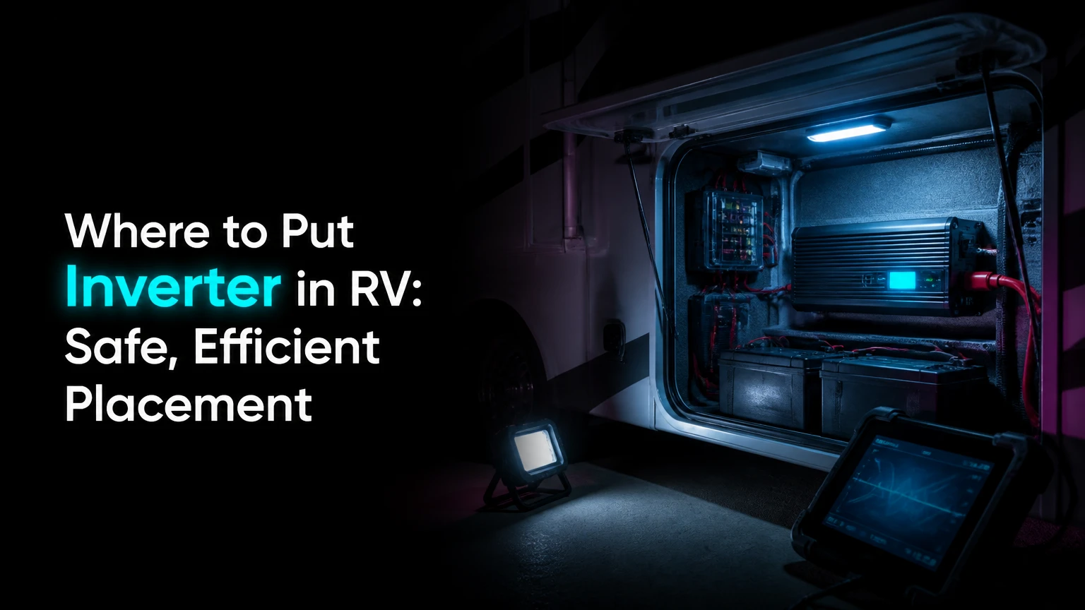
The best place to put an RV inverter is in a dry, ventilated, serviceable compartment as close to the house battery bank as practical, usually within 3-5 feet of the batteries. Keep the inverter separate from flooded lead-acid batteries, protect it from cargo and road spray, and follow the inverter manufacturer’s clearance, orientation, cable, and grounding instructions.
Key Facts at a Glance
- A 2,000-watt inverter can draw approximately 167 amps from a 12-volt battery bank at full rated output, before efficiency losses.
- The inverter should usually be mounted near the batteries, while the 120-volt AC wiring can travel farther with less voltage-drop concern.
- A flooded lead-acid battery compartment must not contain an inverter unless the installation manual and ventilation design specifically permit that arrangement.
- A pass-through bay, electrical compartment, or protected under-bed cabinet can work when the location remains dry, ventilated, structurally secure, and accessible.
- Fuse size depends on inverter instructions, maximum DC current, cable ampacity, and installation standards; 150A, 250A, and 400A are not universal ratings.
- A permanently wired inverter-charger requires correct neutral, ground, transfer-switch, and shore-power integration to prevent dangerous backfeed.
What an RV Inverter Does
An RV inverter converts 12-volt direct-current power from the house batteries into approximately 120-volt alternating-current power for appliances and receptacles. The inverter does not create energy, increase battery capacity, or replace a converter, although an inverter-charger can also charge batteries from shore power or a generator.
A basic inverter powers selected appliances through built-in receptacles or a dedicated AC circuit. An inverter-charger adds a battery charger and transfer-switch function, allowing the RV to switch between shore or generator power and inverter output. That larger system requires more careful AC wiring than a portable plug-in inverter.
The electrical demand rises sharply on the 12-volt side. A 2,000-watt load requires about 167 amps at 12 volts under ideal conditions, and roughly 185 amps after allowing for typical inverter losses. A microwave, coffee maker, induction plate, or hair dryer can therefore expose weak cables, loose terminals, and undersized batteries quickly.
Where to Put Inverter in RV
The best RV inverter location combines four conditions: short battery cables, continuous cooling airflow, protection from moisture and impact, and enough working room to service terminals and fuses. A front pass-through bay usually fits travel trailers and fifth wheels, while a dedicated electrical bay often fits motorhomes with factory battery and AC equipment nearby.
The shortest possible DC route normally matters more than placing the inverter beside the appliances. Long 120-volt AC wiring is generally easier to manage than long, high-current 12-volt wiring because the DC side carries far more current at the same power level.
Victron Energy installation guidance uses the practical rule, “Keep the cables as short as possible.” The exact acceptable distance still comes from the inverter manual, cable-size calculation, and maximum current rather than from a universal 3-foot rule.
Placement Options Compared
| RV location | Typical battery distance | Ventilation requirement | Main trade-off |
|---|---|---|---|
| Front pass-through bay | 2-6 feet | Passive vents or open airflow | Cargo can damage terminals or cables |
| Dedicated electrical bay | 1-5 feet | Manufacturer clearance plus heat exit | Existing equipment may limit access |
| Under-bed cabinet | 3-8 feet | Louvered openings, 3-5 inches around vents | Interior noise and heat |
| Under-dinette compartment | 4-10 feet | Intake and exhaust airflow | Cable routing can become expensive |
| Battery-adjacent exterior box | 1-3 feet | Weather protection and battery separation | Road spray, corrosion, and temperature |
A pass-through compartment is often the best compromise for a travel trailer because it provides a strong mounting surface and short cables. Add a rigid guard or partition if storage can shift against the inverter, fan openings, fuse holder, or battery lugs.
An interior cabinet can be better in freezing climates because lithium batteries and electronic components avoid severe temperature swings. The cabinet must not become an airtight box, and sleeping occupants may notice fan noise when the inverter operates overnight.
How Close Should the Inverter Be to the Batteries?
Place the inverter as close to the battery bank as the installation allows, with 3-5 feet of one-way cable as a practical target for many 12-volt systems. The relevant measurement is the complete DC circuit length, meaning the positive and negative paths together, unless the manufacturer’s voltage-drop table specifies another method.
A 15-foot one-way run creates a 30-foot circuit before considering connection resistance. At approximately 185 amps, that length can require very large conductors and still produce low-voltage shutdowns during microwave or compressor startup.
The inverter does not need to be close to the RV distribution panel for the same reason. Install the DC equipment near the batteries, then route properly protected AC conductors to a subpanel, transfer switch, or dedicated receptacle circuit.
Typical 12-Volt Current and Cable Planning
| Inverter rating | Approximate DC current at full load | Typical copper cable range for short runs | Typical overcurrent range |
|---|---|---|---|
| 1,000 watts | 90-100A | 2 AWG to 1/0 AWG | 125-150A |
| 1,500 watts | 135-150A | 1/0 AWG to 2/0 AWG | 175-200A |
| 2,000 watts | 180-200A | 2/0 AWG to 4/0 AWG | 225-300A |
| 3,000 watts | 275-300A | 4/0 AWG or parallel conductors | 350-400A |
These are planning ranges, not installation instructions. Temperature rating, cable insulation, conductor length, terminal type, allowable voltage drop, battery short-circuit current, and the inverter manual can change the required conductor and fuse.
Which RV Compartment Is Best?
A dedicated electrical compartment is the best location for a permanently wired inverter-charger when the compartment has adequate airflow, remains dry, and already contains the transfer switch, AC subpanel, busbars, or battery disconnect. Factory electrical bays reduce cable crossings and make future service easier.
A front pass-through bay is usually the best location for a retrofit in a travel trailer or fifth wheel. It works especially well when the batteries sit on the trailer tongue or in a front battery compartment, but cargo restraint and water intrusion require attention.
An under-bed or under-dinette compartment is appropriate when the batteries are inside or nearby and the inverter manual allows indoor mounting. The enclosure needs a rigid barrier from clothing, bedding, tools, and stored cargo, with ventilation openings sized for the inverter’s required airflow.
| Location | Best application | Minimum design checks | Do not use when |
|---|---|---|---|
| Front pass-through | Travel trailer retrofit | Dry floor, protected cables, cargo barrier | Water enters during towing |
| Electrical bay | Class A or Class C inverter-charger | AC access, heat clearance, service access | Fans exhaust into a sealed cavity |
| Under-bed cabinet | Small motorhome or van | Vent openings, structural floor, noise control | Bedding blocks intake or exhaust |
| Under-dinette seat | Compact installation | Short cable route, partition, removable panel | Occupants cannot access the disconnect |
| Exterior battery box | Only with approved design | Separate battery compartment, weather sealing | Flooded batteries share sealed airspace |
Can an Inverter Share a Compartment With Batteries?
An inverter should not share a sealed compartment with flooded lead-acid batteries because charging can release hydrogen gas and inverter switching components can provide an ignition source. Sealed AGM batteries reduce gas release during normal operation, but they do not justify ignoring the battery manufacturer’s ventilation and separation requirements.
Lithium iron phosphate batteries generally do not emit hydrogen during normal charging, yet they still need temperature control, overcurrent protection, and a battery-management system. A lithium battery can disconnect abruptly under low temperature, overcurrent, or fault conditions, causing an inverter to shut down even when the battery voltage appears normal.
Never mount an inverter directly above a flooded battery. Acid mist and corrosion can attack circuit boards, fasteners, and cable connections. If the battery bay is the only short-cable route, use a separate ventilated compartment or consult a qualified RV electrical technician about a compliant enclosure.
How Should You Mount the Inverter?
Mount the inverter to a rigid structural surface with the orientation, clearance, and airflow specified in its manual. Use bolts, machine screws with backing hardware, or suitable structural fasteners rather than relying on thin wall paneling, because road vibration can loosen a heavy inverter and damage its terminals.
Many inverters mount on a vertical wall or horizontal floor, but some models restrict orientation or require fans to face a specific direction. Maintain at least the manufacturer’s stated clearance; when no value is published, 3 inches around the case and 5 inches near fan openings provide a conservative planning baseline, not a substitute for the manual.
Keep the inverter away from direct engine heat, water leaks, furnace ducts, battery acid, and compartments that exceed its rated ambient temperature. Leave enough room to remove covers, torque terminals, replace a fuse, and read fault indicators without dismantling cabinetry.
Installation Checklist Before Drilling
- Confirm the inverter’s continuous, surge, and charger ratings.
- Measure the one-way and complete DC cable paths.
- Identify the battery disconnect, main fuse, and chassis-ground point.
- Check every wall and floor for wiring, plumbing, propane lines, and structural framing.
- Confirm the compartment stays dry during rain and road spray.
- Plan AC routing separately from low-voltage data, audio, and antenna cables.
- Check whether the installation requires a transfer switch or dedicated subpanel.
- Read the inverter, battery, and RV manufacturer manuals before connecting power.
How Do You Wire an RV Inverter Safely?
Wire an RV inverter by isolating every power source, installing DC overcurrent protection at the battery, connecting short heavy-gauge conductors, bonding the chassis correctly, and integrating AC output through an approved transfer switch or dedicated circuit. A permanently wired inverter-charger should be installed by a qualified person familiar with RV shore-power systems.
Step 1: Isolate Every Power Source
Disconnect shore power, stop the generator, turn off solar charging, and open the battery disconnect. Remove the negative battery cable, then verify with a multimeter that the inverter DC terminals are not energized.
A solar controller can continue producing battery voltage even when shore power is disconnected. Covering panels or opening the solar disconnect may be necessary during installation.
Success checkpoint: The inverter DC terminals measure zero volts relative to the chassis.
Common mistake: Disconnecting only shore power while solar or the generator remains connected.
Step 2: Mount the DC Fuse Near the Battery
Install the fuse or breaker specified by the inverter manufacturer in the positive conductor as close to the battery as practical. A common planning limit is within 18 inches, but the protected cable length and applicable installation requirements determine the final position.
A Class T fuse is often selected for high-current lithium and inverter systems because it offers high interrupt capability. A breaker can provide convenient reset and disconnect functions, but its interrupt rating and DC suitability must match the battery system.
Success checkpoint: A short section of positive cable exists between the battery terminal and the overcurrent device, with no unprotected cable routed through the RV.
Common mistake: Choosing a fuse solely from the inverter wattage table without checking cable ampacity.
Step 3: Run and Terminate the DC Cables
Run equal-length, flexible copper positive and negative cables where possible, protecting them from abrasion with loom, conduit, grommets, or secured clamps. Route the positive cable through the fuse, then to the inverter positive terminal; connect the negative cable directly to the inverter negative terminal or to an approved negative busbar.
Cable lugs must fit the stud diameter, conductor size, and crimp profile. Torque every terminal to the manufacturer’s specification, because loose high-current connections generate heat and can fail without immediately blowing the fuse.
Success checkpoint: Cables cannot rub, flex against sharp edges, or move at the terminals.
Common mistake: Using automotive jumper cable or undersized audio cable with unknown continuous ampacity.
Step 4: Bond the Chassis Ground
Connect the inverter chassis-ground lug to the RV chassis using the conductor size specified by the inverter and installation standard. An 8 AWG copper bonding conductor is common in some installations, but it is not a universal requirement for every inverter.
The chassis bond provides a low-resistance fault path so protective devices can operate if an internal conductor contacts the metal case. The DC negative connection and chassis bond have different functions, so do not assume one replaces the other.
Success checkpoint: The ground lug is clean, tight, protected from corrosion, and connected to substantial bare-metal chassis structure.
Common mistake: Attaching the ground wire to a painted cabinet screw or thin sheet-metal trim.
Step 5: Connect the AC Output Correctly
Use the inverter’s receptacle for a simple appliance-only installation, or connect the output to a dedicated subpanel through the manufacturer-approved transfer equipment. An inverter output must never be connected to an energized shore-power circuit without proper switching, because backfeeding can energize campground wiring and injure workers.
An inverter-charger with an internal or external transfer switch can power selected RV circuits automatically. Keep high-demand loads such as electric water heaters, air conditioners, and electric heating elements outside the inverter-backed circuits unless the battery, inverter, and wiring were designed for them.
Success checkpoint: Shore, generator, and inverter sources cannot energize the same circuit simultaneously.
Common mistake: Plugging the inverter into an RV wall outlet to energize the entire coach.
Pure Sine Wave Inverter or Inverter-Charger?
A pure sine wave inverter is the safer general-purpose choice for sensitive electronics, induction motors, chargers, audio equipment, and appliances with electronic controls. An inverter-charger costs more and requires more installation work, but it adds shore-power charging and automatic source transfer.
Modified sine wave models can run some resistive loads, such as basic heaters or incandescent lamps, but they may create extra heat, audible hum, reduced motor performance, or charger incompatibility. The low purchase price does not eliminate the need for correctly sized DC cables and overcurrent protection.
| System type | Typical output | Installation complexity | Best use |
|---|---|---|---|
| Plug-in modified sine wave | 300-1,000W | Low, 15-60 minutes | Small resistive loads |
| Plug-in pure sine wave | 600-1,500W | Low, 15-60 minutes | Laptop, television, small appliances |
| Hard-wired pure sine wave | 1,000-3,000W | Moderate, 4-8 hours typical | Dedicated RV circuits |
| Inverter-charger | 2,000-3,000W | High, 6-12 hours typical | Whole-coach selected circuits |
| High-output system | 3,000W or more | High, professional design often needed | Large battery banks and specialized loads |
An inverter is not a practical substitute for a generator when the intended load is a rooftop air conditioner running for many hours. Air-conditioning startup current, battery capacity, alternator charging limits, heat, and cable size can make that design costly and heavy.
What Battery and Load Factors Change the Location?
Battery chemistry, inverter power, climate, and appliance duty cycle can change the best location. A 1,000-watt weekend system may use a protected bay and dedicated extension lead, while a 3,000-watt inverter-charger needs a short high-current route, substantial battery bank, large fuse, and properly engineered AC distribution.
Lithium batteries tolerate frequent cycling better than many lead-acid systems, but lithium cells still have charging-temperature limits and can disconnect through the BMS. Flooded batteries require ventilation and inspection access, while AGM batteries require less routine maintenance but still need protection from overcharging and heat.
| Use case | Typical inverter | Practical location | Important limitation |
|---|---|---|---|
| Laptop, television, camera chargers | 600-1,000W | Interior cabinet or short-cable bay | Avoid unnecessary whole-panel wiring |
| Coffee maker or microwave | 1,500-2,000W | Battery-adjacent bay | Battery bank may exceed 150A draw |
| Hair dryer and kitchen loads | 2,000-3,000W | Electrical compartment | Do not combine several high loads |
| Air conditioner | 3,000W or more | Engineered interior or electrical bay | Battery capacity and startup surge dominate |
| Solar-supported boondocking | 1,000-3,000W | Near battery and DC bus | Solar replenishment may lag consumption |
A 2,000-watt inverter can consume approximately 185 amps while operating a 2,000-watt AC load at realistic efficiency. One 100Ah battery may provide the current briefly, but voltage sag and BMS limits can cause shutdown before the battery’s rated amp-hours are used.
What Does RV Inverter Installation Cost?
A typical DIY RV inverter installation costs approximately $250-$700 for cables, lugs, fuse hardware, disconnects, conduit, and mounting materials, excluding the inverter. Professional installation commonly adds $300-$800 for a straightforward retrofit and more for an inverter-charger with a new subpanel.
The project usually takes 4-8 hours when the battery location, cable path, and AC design are straightforward. A complex motorhome installation with concealed wiring, multiple AC circuits, solar integration, or battery relocation can take 8-16 hours.
| Installation type | Hardware excluding inverter | Typical labor | Typical duration |
|---|---|---|---|
| Plug-in 600-1,000W | $30-$120 | $0-$150 | 15-60 minutes |
| Hard-wired 1,000-1,500W | $150-$350 | $300-$600 | 4-6 hours |
| Hard-wired 2,000W | $250-$600 | $400-$900 | 5-10 hours |
| 2,000-3,000W inverter-charger | $400-$1,000 | $600-$1,500 | 8-16 hours |
| Complex whole-coach retrofit | $700-$1,500 | $1,000-$2,500 | 12-24 hours |
Prices vary by region, cable length, copper pricing, access, and whether an electrician must correct existing RV wiring. A low quoted price deserves scrutiny if it excludes the DC fuse, chassis bonding, transfer switch, or commissioning tests.
Common Location Problems and Fixes
An RV inverter that shuts down under load usually has low battery voltage at the inverter terminals, excessive cable resistance, a weak battery, or a load above the continuous rating. Measure voltage directly at the inverter while starting the microwave or other high-demand appliance, rather than relying on a battery monitor several feet away.
An inverter that overheats usually has blocked intake or exhaust openings, excessive ambient temperature, insufficient cabinet volume, or a failed fan. Relocate stored items, increase louvered airflow, and compare the compartment temperature with the inverter’s rated operating range before adding a fan.
| Symptom | Likely cause | Diagnostic check | Corrective action |
|---|---|---|---|
| Low-voltage alarm | Long or undersized DC cables | Measure inverter terminals under load | Shorten route or increase conductor size |
| Thermal shutdown | Blocked airflow or hot bay | Check fan openings and ambient temperature | Add clearance or relocate inverter |
| Fuse opens immediately | Short circuit or wrong fuse | Isolate load and inspect polarity | Repair wiring, then use specified fuse |
| AC outlets remain dead | Incorrect transfer-switch wiring | Test input and output separately | Rewire through approved switching |
| Buzzing audio equipment | Conducted or radiated interference | Turn inverter off and compare noise | Separate signal and power wiring |
| Battery drains quickly | Excessive standby or appliance load | Record DC current with clamp meter | Disable inverter when unused |
A voltage reading of 12.6 volts at the battery does not prove the inverter receives adequate voltage under load. A poor lug crimp or corroded disconnect can create a large voltage drop even when open-circuit battery voltage looks normal.
What Are the Most Important Installation Mistakes?
The most damaging mistakes are placing the inverter in a wet or sealed compartment, running long undersized DC cables, omitting battery-side overcurrent protection, and connecting AC output without preventing backfeed. Correcting the location before final wiring is cheaper than replacing an overheated inverter or damaged battery cable.
Experienced installers also avoid three less obvious errors:
- Sizing from nominal watts alone: A 2,000-watt inverter can demand nearly 200 amps at 12 volts, so cable, fuse, battery, and disconnect ratings must be considered together.
- Measuring cable distance one way only: Voltage drop applies to the positive and negative circuit path, not merely the visible positive cable.
- Treating ventilation as free space: A 3-inch gap is ineffective if a cabinet door blocks the fan’s intake or the hot exhaust recirculates into the same cavity.
An honest limitation matters here. No inverter location can compensate for a battery bank that lacks the amp-hour capacity, discharge rating, or temperature capability required by the intended appliances.
Where Should Different RV Owners Install an Inverter?
Weekend campers should usually install a 600-1,500-watt pure sine wave inverter near the batteries and power selected appliances through the inverter’s receptacles or a dedicated interior outlet. Full-time boondockers generally need a hard-wired 2,000-3,000-watt inverter-charger in an electrical bay with a transfer switch and battery monitor.
Small van owners often prefer an under-seat or under-bed installation because the battery, inverter, and DC bus can remain close together. Owners in extreme heat should prioritize a shaded, ventilated electrical compartment over a tightly sealed interior cabinet, provided the compartment stays within the inverter’s temperature rating.
Travel Trailer or Fifth Wheel
Use the front pass-through bay when the batteries are on the tongue or in the front storage area. Install a rigid plywood or metal mounting panel, protect the inverter from cargo, and route cables through abrasion-resistant bushings.
Class B or Class C Motorhome
Use the factory electrical bay when it is close to the house batteries and has room for AC switching. If the batteries are under the bed, an adjacent ventilated cabinet can reduce cable length, but the inverter must remain accessible for inspection.
Lithium Battery Retrofit
Place the inverter near the lithium battery and main positive and negative busbars, not necessarily directly beside one battery. Include the battery disconnect, Class T fuse or approved alternative, shunt, temperature sensors, and BMS wiring according to the battery manufacturer’s diagram.
FAQ
Can an RV inverter be mounted in an exterior compartment?
Yes, an RV inverter can occupy an exterior compartment when the model is approved for that environment and the compartment protects it from rain, road spray, condensation, extreme heat, and cargo impact. Exterior mounting often improves service access, but an unsealed bay can shorten inverter life through corrosion.
Should the inverter be near the battery or the electrical panel?
The inverter should usually be near the battery because the 12-volt side carries much higher current than the 120-volt side. Place the AC subpanel or transfer switch where the RV wiring permits, then keep the DC conductors short, secured, fused, and protected from abrasion.
Can I install an RV inverter beside AGM batteries?
An inverter should not be placed in a sealed battery compartment beside AGM batteries unless the battery and inverter manufacturers approve the arrangement and the compartment has suitable ventilation. AGM batteries release less gas than flooded batteries, but abnormal charging or failure can still create safety concerns.
Does an RV inverter need its own battery?
An RV inverter needs a suitable house battery bank or approved DC energy source with enough voltage, discharge current, and capacity for the intended load. The chassis starting battery should not power a large house inverter unless the vehicle manufacturer and system design specifically provide that function.
Can an inverter run an RV refrigerator?
An RV inverter can run a residential compressor refrigerator when the inverter has sufficient continuous and startup capacity and the battery bank can support the refrigerator’s daily energy use. A three-way absorption refrigerator normally uses propane for off-grid operation, while its 120-volt heater can consume substantial power.
How do I know whether my inverter cable is too small?
Measure voltage at the inverter DC terminals while a high-load appliance starts. If inverter voltage falls sharply while battery voltage remains much higher, excessive cable resistance, a poor connection, a weak disconnect, or an undersized conductor is likely; inspect every high-current connection before replacing the inverter.
The Bottom Line
The answer to where to put inverter in RV is usually a dry, ventilated, structurally secure compartment within 3-5 feet of the house batteries, with the shortest practical complete DC circuit and clear service access. A front pass-through bay suits many trailers, a dedicated electrical bay suits hard-wired motorhome systems, and an interior cabinet works only when airflow, temperature, battery separation, and cargo protection are properly engineered.