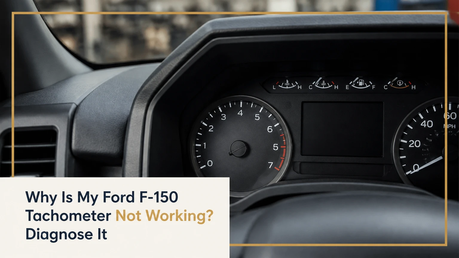
A Ford F-150 tachometer usually stops working because the instrument cluster has lost power, the gauge mechanism has failed, the PCM is not receiving engine-speed data, or the communication wiring is interrupted. Compare live engine RPM with the dead gauge first: that single test separates an engine-speed fault from a cluster or network fault.
Key Facts at a Glance
- The tachometer displays engine speed in revolutions per minute, or RPM.
- A scan tool can read the Ford F-150 PCM’s calculated engine RPM independently of the dashboard needle.
- Accurate scan-tool RPM with a needle at zero points toward the cluster, cluster power, or network wiring.
- Zero scan-tool RPM, P0335, or an engine that stalls and will not restart makes the CKP circuit more likely.
- Fuse numbers differ by model year, engine, trim, and fuse-box location; use the truck’s fuse chart rather than a generic number.
- A cluster self-test checks gauge movement, but a passing sweep does not prove that the RPM data path works.
Why Is My Ford F-150 Tachometer Not Working?
The most likely fault depends on whether the F-150 engine runs normally, whether the scan tool sees RPM, and whether other cluster functions work. A dead tachometer with normal engine operation commonly indicates a cluster stepper motor, solder joint, connector, fuse, ground, or CAN communication problem; a dead tachometer with stalling or no-start symptoms raises CKP and PCM signal faults.
The tachometer is not usually connected directly to a modern ignition coil. The CKP sensor detects crankshaft position, the PCM calculates engine speed, and the instrument cluster receives that value through the vehicle network. Older F-150s use different signal arrangements, so a 1994 truck cannot be diagnosed with the same assumptions as a 2018 truck.
What symptoms identify the likely fault?
| Tachometer symptom | Other vehicle behavior | Most likely area | First confirmation |
|---|---|---|---|
| Needle remains at 0 RPM | Engine runs smoothly | Cluster, fuse, network | Scan live RPM |
| Needle drops while driving | Engine stumbles or stalls | CKP circuit, wiring, PCM input | Record RPM during failure |
| Needle jumps or sticks | Engine runs normally | Stepper motor or PCB | Cluster self-test |
| Tachometer and odometer fail | Other warning lamps may disappear | Cluster power, ground, PCB | Fuse and voltage checks |
| Failure follows battery replacement | Engine starts normally | Cluster software or power event | Scan modules and inspect terminals |
| Tachometer works cold, fails warm | Engine may remain normal | Cluster solder joint or stepper motor | Heat-related repeat test |
An intermittent gauge deserves more attention than a permanently dead needle. Heat expansion can open a cracked solder joint, while vibration can interrupt a damaged connector terminal. Photographing the symptom and recording scan-tool RPM during the event often prevents an unnecessary sensor replacement.
How Does the F-150 Tachometer Get Its Signal?
The Ford F-150 tachometer receives engine-speed information through a generation-specific electronic path. On many later trucks, the CKP sensor sends a position waveform to the PCM, the PCM calculates RPM, and the instrument cluster moves the needle or updates the digital display after receiving network data.
The CKP sensor does not directly “drive” the dashboard gauge in the simple way older ignition systems sometimes did. The PCM uses crankshaft position intervals to calculate rotational speed, then communicates with other modules over a Ford vehicle network. SAE J1979 identifies engine speed as OBD-II data parameter 0C, although scan-tool availability and module access vary by vehicle year.
What can interrupt the signal chain?
| Signal stage | Component | Typical failure | Result |
|---|---|---|---|
| Position detection | CKP sensor and reluctor wheel | Open circuit, contamination, damaged connector | No or unstable RPM calculation |
| Signal processing | PCM | Input fault, power loss, software issue | Engine-speed data missing |
| Network transmission | CAN wiring, terminating circuits, gateway modules | Short, corrosion, lost communication | Cluster may show zero or other warnings |
| Cluster input | Instrument cluster connector and PCB | Loose terminal, cracked solder | One or several gauges fail |
| Gauge movement | Analog stepper motor or display electronics | Sticking motor, failed driver circuit | RPM data exists but display is wrong |
A scan tool that communicates only with the engine computer may not identify a cluster communication fault. A professional scan tool that accesses the instrument cluster, body modules, and gateway can retrieve U-codes and compare module data more completely.
What Should You Test First?
Test live engine RPM before replacing a CKP sensor or removing the instrument cluster. Connect an OBD-II scanner, start the engine, and compare the displayed RPM with the dashboard; an accurate scanner reading with a dead needle strongly shifts the diagnosis toward the cluster, its power supply, or vehicle-network communication.
Use a scanner that displays live data, not merely one that reads generic fault codes. SAE J1979 PID 0C is the relevant generic engine-speed parameter, but a Ford-capable scanner may provide more useful module-level information.
Step 1: Confirm the symptom
Start the truck and observe the tachometer at idle, during a gentle increase to approximately 2,000 RPM, and during a short road test if safe. Note whether the needle is fixed at zero, moves erratically, responds slowly, or fails only after the cabin warms.
Check the engine simultaneously. Rough running, stalling, hard starting, a no-start condition, or a sudden loss of power changes the priority from gauge diagnosis to engine-speed signal diagnosis.
Step 2: Read live RPM
With the engine running, compare scanner RPM with the tachometer. A normal warm idle commonly falls near 600-800 RPM, but the correct value depends on engine, temperature, load, and calibration.
- Scanner reads approximately 650 RPM, dashboard reads 0: investigate cluster and network circuits.
- Scanner reads 0 RPM while cranking: investigate CKP power, ground, signal, wiring, and PCM input.
- Scanner RPM jumps while the engine runs unevenly: investigate CKP signal integrity and reluctor-related faults.
- Both readings disappear briefly: capture the event with a graphing scanner and inspect shared power or ground circuits.
Step 3: Scan stored and pending codes
Look for P0335 and related CKP circuit codes, P0320 engine-speed input codes, and U0155 lost communication with the instrument panel cluster. Code definitions and applicability vary, so a code identifies a circuit or communication concern, not automatically a failed part.
Clear codes only after recording freeze-frame data. If a fault returns during a controlled test, the return conditions can distinguish a heat-sensitive cluster fault from a crankshaft signal fault.
Is the CKP Sensor Really the Problem?
A faulty CKP sensor is plausible when the Ford F-150 tachometer is dead and the engine cranks without starting, stalls unexpectedly, or shows zero or implausible RPM on a scan tool. A CKP sensor is not the first suspect when the engine runs normally and a scanner reports stable RPM, because the PCM is already receiving usable engine-speed information.
The sensor may still have an intermittent wiring defect even when the engine currently runs. Inspect the connector near the sensor, look for oil saturation or rubbed insulation, and perform a wiggle test while monitoring live RPM. Do not disconnect a sensor with the ignition on unless the applicable Ford service procedure permits it.
| Diagnostic result | CKP probability | Recommended next test | Avoid |
|---|---|---|---|
| Zero RPM during cranking | High | Check sensor power, ground, waveform, and wiring | Buying a sensor immediately |
| Stable 700 RPM at idle | Low for a complete CKP failure | Test cluster and network | Replacing CKP blindly |
| RPM drops to zero during stall | High | Capture waveform and connector movement | Assuming the PCM failed |
| Tachometer fails alone | Low | Run cluster self-test | Chasing ignition coils first |
| P0335 returns with no-start | Medium to high | Verify circuit resistance and waveform | Relying on code alone |
A multimeter can detect power, ground, and some resistance faults, but an oscilloscope provides stronger evidence because it shows the CKP waveform while cranking or during an intermittent failure. Ford service information specifies the correct circuit tests for the exact engine and year.
Which Fuses and Grounds Matter?
The correct fuse is the instrument-cluster fuse listed for the specific F-150 year, engine, cab, and trim. Fuse positions cited for one generation cannot safely be applied to another, so use the owner’s manual, the fuse-box cover, or Ford service information and test both fuse terminals with the circuit powered.
A visual fuse inspection is insufficient. A fuse can appear intact while its terminal is loose, and a replacement fuse will fail again if a short remains. Use a test light or multimeter, connect the ground lead to a known-good chassis ground, and verify power on both sides of the fuse.
Inspect these areas:
- Instrument-cluster fuse and ignition-feed fuse.
- Battery terminals and body ground near the battery.
- Cluster connector pins for pushed-back, oxidized, or overheated terminals.
- Ground straps between the engine, body, and frame.
- Aftermarket remote-start, alarm, stereo, or gauge wiring.
If several gauges, the odometer, or warning lamps fail together, shared power or ground is more likely than several independent stepper motors failing at once. Disconnect the battery according to Ford’s safety procedure before removing trim, and allow airbag-system discharge time where required.
Can a Cluster Self-Test Prove the Gauge Is Bad?
A Ford F-150 instrument-cluster self-test can prove that the needle or display hardware fails to respond, but the test cannot prove that the CKP sensor, PCM, or network is healthy. The button sequence varies by year and cluster design, so the owner’s manual or Ford workshop procedure takes priority over a universal key combination.
Many F-150 clusters enter a test or engineering mode by holding an instrument-panel button while switching the ignition to RUN, without starting the engine. Some use the odometer reset, trip button, steering-wheel controls, or a specific Setup and Reset sequence.
During the test, observe whether the tachometer sweeps smoothly and returns to its baseline. A failed sweep supports a cluster motor, PCB, or display fault. A smooth sweep means the physical gauge can move, but the live RPM input still requires separate testing.
Do not force the needle by hand. The stepper motor’s zero position and calibration can be disturbed, and some digital clusters require module-specific procedures rather than a mechanical sweep test.
How Do F-150 Generations Change the Diagnosis?
F-150 tachometer diagnosis changes substantially across model years because the truck moved from hardwired ignition-speed signals to networked module communication and, later, integrated digital displays. Year-specific wiring diagrams and fuse charts are mandatory, especially when a repair involves cluster replacement or module programming.
| F-150 era | Common tachometer architecture | Frequent fault pattern | Best first test |
|---|---|---|---|
| 1992-1996 | Analog ignition or coil-related input | Open signal wire, cluster circuit fault | Verify ignition-speed signal and cluster power |
| 1997-2003 | Electronic cluster with Ford SCP communication | Cracked solder joints, connector faults, odometer blackout | Cluster self-test and connector inspection |
| 2004-2008 | Cluster stepper motors and network data | Failed stepper motor, PCB fault, communication issue | Live RPM plus gauge sweep |
| 2009-2014 | CAN-connected instrument cluster | Network wiring, cluster power, module faults | Full-module scan and voltage checks |
| 2015-2020 | CAN network with revised cluster electronics | Cluster, gateway, software, or wiring fault | Ford-capable scan and network diagnosis |
| 2021-present | Digital instrument display and networked modules | Display electronics, module communication, software | Module scan, battery test, software verification |
The boundaries above describe broad diagnostic eras, not a substitute for a wiring diagram. Engine swaps, fleet packages, mid-year changes, and trim-specific clusters can alter the actual circuit.
Is the Instrument Cluster or Stepper Motor Faulty?
The instrument cluster or its stepper motor is the leading suspect when the engine runs normally, live scan data shows correct RPM, and the tachometer fails its self-test. Older analog clusters can develop cracked solder around connector pins or motor terminals, while later assemblies may have failed stepper motors, driver circuits, display electronics, or internal communication faults.
A single dead gauge points more strongly toward that gauge’s motor or circuit. A dead tachometer combined with an odometer blackout, warning-lamp loss, or several dead gauges points toward cluster power, ground, connector, or PCB-level failure.
What does a cluster inspection reveal?
Remove the cluster only with the battery and airbag precautions specified by Ford. Inspect connector pins under magnification, look for heat discoloration, and check for cracked solder rings around high-stress terminals. Do not assume every visible dull solder joint is defective.
Stepper-motor replacement is an electronics repair, not a guaranteed plug-in procedure. The replacement part must match the cluster design, the PCB pads must remain intact, and the needle must be refitted at the correct zero position. A temperature-controlled electronics iron is appropriate; a high-wattage plumbing iron can lift copper traces and permanently damage the board.
An honest limitation matters here: cluster repair is not suitable when the PCB is delaminated, the display driver is damaged, or the technician cannot preserve calibration and mileage records. A professional rebuilder may be safer than a low-cost motor kit.
How Much Does an F-150 Tachometer Repair Cost?
Typical F-150 tachometer diagnosis costs $80-$180, a CKP sensor repair often totals $150-$400, cluster repair commonly costs $150-$350 plus removal, and a new programmed cluster can reach $700-$1,200. Regional labor rates, access difficulty, programming requirements, and the exact model year create wider variation than the component price alone.
These are typical independent-repair ranges, not a Ford Motor Company price list. Obtain a written quote that separates diagnosis, removal, repair, programming, core charges, and odometer documentation.
| Repair route | Typical parts cost | Typical labor or service | Typical total |
|---|---|---|---|
| Fuse, terminal, or ground repair | $5-$40 | $80-$180 | $85-$220 |
| CKP sensor replacement | $35-$150 | $100-$250 | $150-$400 |
| Mail-in cluster rebuild | $100-$250 | $50-$150 removal | $150-$400 |
| Local cluster repair | $150-$450 | Included or $100-$250 | $150-$700 |
| New OEM cluster | $500-$950 | $150-$300 plus programming | $700-$1,200 |
| Used cluster and configuration | $75-$350 | $150-$400 | $225-$750 |
A mail-in rebuild can preserve the original odometer assembly, but the truck may be unavailable while the cluster is away. A new cluster can provide a cleaner warranty path, although configuration and vehicle-specific programming may be required.
Should You Repair, Replace, or Use a Used Cluster?
Repair the original cluster when live RPM is correct, the self-test fails, and the PCB or stepper motor is serviceable. Replace the assembly when the board or display is beyond repair, but treat used-cluster installation as a programming and configuration job rather than a simple swap.
Ford security architecture varies by year and module arrangement. A used cluster may require As-Built configuration, parameter reset, odometer handling, or compatibility checks; it should not be purchased solely because the connector looks identical.
| Option | Typical downtime | Odometer handling | Programming risk | Best use |
|---|---|---|---|---|
| DIY stepper repair | 1-4 hours | Original mileage retained if successful | Low electronic calibration risk, high damage risk | Skilled electronics owner |
| Professional rebuild | 3-7 business days | Usually retains original data | Low when specialist supports the year | Older or repairable cluster |
| Used cluster | 1-3 days | May show donor mileage | Medium to high | Rare or unavailable original unit |
| New OEM cluster | 1-2 days | Configured to vehicle records | Medium, requires programming | Newer truck with failed electronics |
A replacement cluster should be matched by engineering number, software compatibility, connector configuration, and vehicle options. A locksmith or dealer may be able to perform required programming, but not every generic scan tool can configure every F-150 cluster.
Can You Drive the Truck With No Tachometer?
You can usually drive a Ford F-150 with only a dead tachometer if the engine runs normally, no warning lights indicate a serious fault, the oil-pressure and temperature gauges operate, and scan data confirms stable RPM. You should not continue driving when the engine stalls, the tachometer drops with severe misfire, or multiple cluster functions fail.
A tachometer is useful for detecting overspeed, transmission-shift problems, and an intermittent engine-speed signal. It is not a substitute for oil-pressure or coolant-temperature monitoring. If those indicators are also unreliable, stop driving until the cluster power and warning circuits are repaired.
For a work truck that needs short-term RPM visibility, an OBD-II display can show calculated engine speed. The device is only an alternative display, not a repair, and it may lose data during the same network or power fault affecting the truck.
What Do Multiple Dead Gauges Mean?
Multiple dead gauges usually indicate shared cluster power, ground, connector, PCB, or network failure rather than several unrelated gauge motors. When the odometer, warning lamps, speedometer, and tachometer fail together, begin with battery voltage, fuses, grounds, and module communication.
A weak battery can create misleading network codes after a low-voltage event. With the engine off, a healthy fully charged battery is typically near 12.6 volts; during cranking, voltage should not collapse abnormally, and charging voltage with the engine running commonly falls near 13.5-14.8 volts, depending on operating conditions and smart-charging strategy.
These voltage values guide testing, not replace Ford specifications. A battery test, voltage-drop test, and full-module scan provide stronger evidence than clearing U-codes after a jump-start.
What Are the Most Common Diagnostic Mistakes?
The most expensive mistakes come from replacing a CKP sensor before checking live RPM, using the wrong year’s fuse chart, and installing a used cluster without confirming programming requirements. Each mistake changes the vehicle or parts before the failed circuit has been identified.
- Replacing the CKP sensor by code alone: P0335 identifies a circuit concern. Verify power, ground, wiring, and waveform first.
- Using a generic self-test sequence: Button procedures differ across clusters. Confirm the method for the exact year.
- Installing a junkyard cluster immediately: Compatibility, mileage, configuration, and security procedures may create a second fault.
- Testing fuses visually: Measure both fuse test points with the circuit energized.
- Soldering with a plumbing iron: Excess heat can lift PCB traces and destroy an otherwise repairable board.
- Ignoring aftermarket wiring: Remote starters and audio installations can interrupt ignition, ground, or network circuits.
- Clearing codes before recording freeze-frame data: The useful conditions may disappear before the intermittent fault returns.
One practitioner rule is especially reliable: if scan-tool RPM is stable, stop spending diagnostic time at the crankshaft sensor until cluster and communication checks are complete. The PCM has already demonstrated that it can calculate engine speed.
What Is the Fastest Reliable Diagnostic Sequence?
The fastest reliable sequence takes about 30-90 minutes with a live-data scanner, test light, multimeter, and the correct wiring information. The decisive factor is the comparison between PCM RPM and gauge behavior, followed by a cluster self-test and voltage checks.
- Confirm engine behavior. Record stalling, hard starting, warning lamps, and whether the gauge fails constantly or intermittently.
- Read live RPM. Compare scan-tool RPM with the dashboard at idle and during a brief RPM increase.
- Scan all accessible modules. Record P0320, P0335, U0155, low-voltage codes, and communication codes before clearing anything.
- Test cluster fuses. Use the vehicle-specific chart and measure both sides under load.
- Check battery and grounds. Perform voltage and voltage-drop tests, especially after battery work.
- Run the correct cluster self-test. A failed sweep supports an internal cluster fault.
- Inspect connectors and wiring. Look for corrosion, backed-out terminals, abrasion, and aftermarket splices.
- Test CKP circuits only when indicated. Use the Ford procedure for sensor power, ground, resistance, and waveform.
- Choose repair based on evidence. Rebuild the original cluster, repair wiring, replace the sensor, or program a compatible assembly.
You will know the diagnosis is sound when two independent observations agree, such as stable PCM RPM plus failed gauge sweep, or zero cranking RPM plus a verified CKP signal fault. Parts swapping is slower and less reliable.
What Should You Do Based on the Test Result?
Choose the repair path from the test result, not from the age of the truck alone. A normal scan RPM with a failed sweep supports cluster repair, while missing scan RPM with a no-start condition supports CKP-circuit testing before any cluster work.
| Confirmed result | Appropriate repair | Typical cost | Expected time |
|---|---|---|---|
| Blown fuse with repaired short | Repair short and replace fuse | $85-$300 | 1-3 hours |
| Stable RPM, failed sweep | Cluster or stepper repair | $150-$700 | 1 hour to 7 days |
| Zero RPM, verified CKP circuit fault | Sensor or harness repair | $150-$500 | 1-3 hours |
| U0155 with good cluster power | Network or module diagnosis | $150-$600 | 1-4 hours |
| Damaged PCB or display | Rebuilt or new cluster | $300-$1,200 | 1-7 days |
| Intermittent voltage event | Battery, ground, or charging repair | $100-$500 | 1-3 hours |
A dealer is often justified for newer digital clusters requiring proprietary configuration. An automotive electrical specialist may offer better value for an older cluster with a known PCB or stepper-motor fault.
FAQ
Will a bad alternator make the F-150 tachometer stop working?
A charging-system fault can cause cluster resets, erratic gauges, and communication codes when system voltage becomes unstable. Test the battery, charging voltage, and voltage drop before condemning the tachometer. If the engine runs normally and voltage remains stable, an isolated dead needle is more likely an internal cluster or signal-display fault.
Why does the tachometer work after hitting the dashboard?
A temporary response after tapping the cluster suggests a cracked solder joint, loose connector terminal, or failing stepper motor. The impact changes mechanical or electrical contact briefly, but it does not repair the fault. Repeated tapping can damage the PCB, so document the symptom and inspect the cluster properly.
Can a bad ignition coil cause a dead tachometer?
A single bad ignition coil usually causes a misfire, not a permanently dead tachometer. A coil failure can make engine speed fluctuate, while a shared ignition or PCM power fault can create broader symptoms. Compare scanner RPM with the gauge before connecting the tachometer symptom to an ignition component.
Does disconnecting the battery reset the tachometer?
Battery disconnection can clear temporary module states, but it cannot repair a failed stepper motor, broken wire, blown fuse, or damaged PCB. Low voltage during reconnection can also create communication codes. Record existing codes and radio or vehicle settings before disconnecting the battery.
Is a tachometer repair covered by Ford warranty?
Warranty coverage depends on the truck’s in-service date, mileage, warranty plan, and the diagnosed cause. A factory defect in a cluster may qualify, while damage from aftermarket wiring, corrosion, or unauthorized repair may not. A Ford dealer can verify coverage from the VIN and document the applicable diagnostic result.
The Bottom Line
The answer to why is my ford f150 tachometer not working is usually found by comparing live PCM RPM with the dashboard reading. Stable scan RPM points to the cluster, fuse, ground, connector, or network; missing scan RPM with stalling or a no-start condition points toward the CKP circuit and PCM input. Confirm that distinction before buying a sensor or cluster.